3-5
3
Installation
3. Connector names
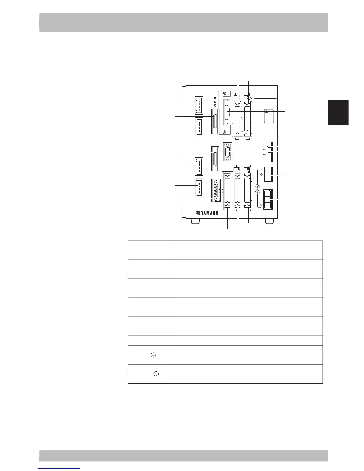
Connector names, locations and functions are shown below.
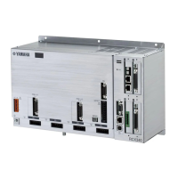
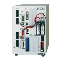
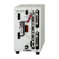
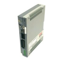
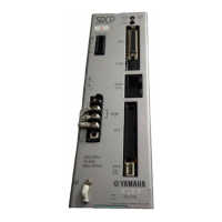
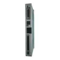
Fig. 3-3-1 RCX connectors
RCX142
MOTOR
XM
YM
ZM
RM
PWR
SRV
ERR
SAFETY
MPB
COM
STD.DIO
RGEN
ACIN
P
N
L
N
ROB
I/O
XY
ROB
I/O
ZR
OP.1 OP.3
OP.2 OP.4
200-230V~
50-60Hz
MAX.2500VA
BATT
ZR
XY
MODEL.
SER. NO.
MANUFACTURED
FACTORY AUTOMATION EQUIPMENT MADE IN JAPAN
注意
CAUTION
取扱説明書参照
READ INSTRUCTION
MANUAL
COM
MPB
SAFETY
XM
YM
ZM
RM
OP.1
OP.3
OP.2
OP.4
RGEN
ACIN
ROBI/O XY
ROBI/O ZR
STD.DIO
BATT
FunctionConnector name
XM/YM/ZM/RM
ROB I/O [XY/ZR]
SAFETY
MPB
COM
STD.DIO
OP.1-4
BATT [XY/ZR]
REGN [P/ /N]
AC IN [L/N/ ]
Connectors for servomotor drive.
Connectors for servomotor feedback and sensor signals.
Input/output connector for safety function such as emergency stop.
Connector for MPB.
RS-232C interface connector.
Connector for dedicated input/output and standard general-purpose
input/output.
Connectors attached to optional expansion I/O boards.
(OP.2 and OP.4 cannot be used with RCX142-T.)
Battery connector for absolute backup.
Connector for regenerative unit.
(Cannot be connected to RCX142-T.)
Terminal block for power cable. Use ring-tongue terminals to make
connections.
w
WARNING
To prevent electrical shocks,
never touch the RGEN and AC IN
terminals when power is
supplied to the robot controller.
 Loading...