En 39
CONNECTIONS
Connecting external components
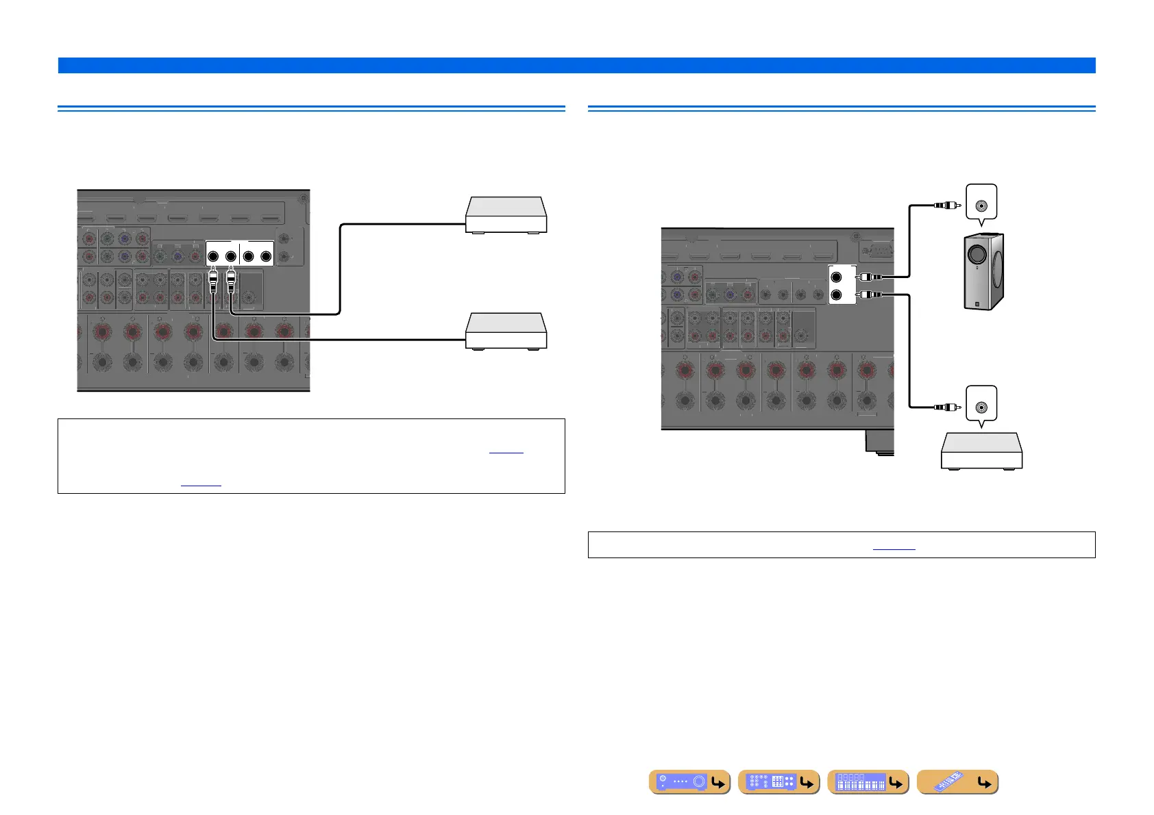
Connecting a SCENE link playback-compatible device
When the components are the Yamaha products and have the capability of the transmission of the
remote control signals, connect the REMOTE IN and REMOTE OUT jacks to the remote control input
and output jack with the monaural analog mini cable as follows.
Using the Trigger function to link external component power
When this unit is connected to a Yamaha subwoofer that supports the system connection or the
component with TRIGGER IN jack, you can turn on and off the component by using this unit.
• When a Yamaha component that supports the SCENE link playback function is connected via the
REMOTE OUT jack, playback begins automatically when the SCENE function is used (☞
p. 54).
• If the component connected to the REMOTE OUT jack is not a Yamaha product, set “SCENE IR” in the
Scene menu to “Off” (☞
p. 107).
IN
12
OUT IN OUT
EM
TE
E
RR
N
RR
ND BA
K
PEAKER
ENTER
V 3
V 5 AV
IN
L
R
NT
-
AV
RR
N
R. BA
K
BW
FE
ENTE
ULTI CH INPU
OMPONENT VIDE
MONITOR OUT/ZONE OU
Z
NE
PRE
ZONE
NE
R. PRE
EN
E
FR
NT
F. P R E
EN
E
RR
ND
R. BA
ENTE
REAR
RI
E
12
0.1
.
(1 BD
DVD
Remote control out
Remote control in
Infrared signal receiver or
Yamaha component
Yamaha component
(CD or DVD player, etc.)
Functions of the TRIGGER OUT jack can be specified (☞p. 130).
2
1
RI
ER
OUT
+12V 0.1A MAX.
XTRA SP1
ONE2/ZONE
F.P R E
EN
E
RR
N
RR
ND BA
K
PEAKER
ENTE
4
INGL
FR
N
-
V 3
4
CK
SUBWOOFE
ENTER
T
E
M
NIT
R
UT
Z
NE
U
NE
U
RE
U
Z
NE
ZONE 3
R. PRE
EN
RONT
F. PRE
EN
B
R
URROUN
UR. BAC
ENTER
REAR
S-232
T
T
REM
T
TRIGGER IN
System connection input
Yamaha subwoofer
that supports the system
connection
Trigger input
Component with the
TRIGGER IN jack
(Power amplifier or
DVD player, etc.)
 Loading...