Ground fault in the output circuit
causing the DC bus capacitor to
overcharge.
• Check the motor wiring for ground faults.
• Correct grounding shorts and turn the power back on.
Drive input power voltage is too
high.
• Check the voltage.
• Lower drive input power voltage within the limits listed in the specifications.
The dynamic braking transistor is
damaged.
Replace the drive.
The braking transistor is wired
incorrectly.
• Check braking transistor wiring for errors.
• Properly rewire the braking resistor device.
Drive fails to operate properly due
to noise interference.
• Review the list of possible solutions provided for controlling noise.
• Review the section on handling noise interference
and check the control circuit
lines, main circuit lines and ground wiring.
Motor hunting occurs.
• Adjust the parameters that control hunting.
• Set the hunting prevention gain (n1-02).
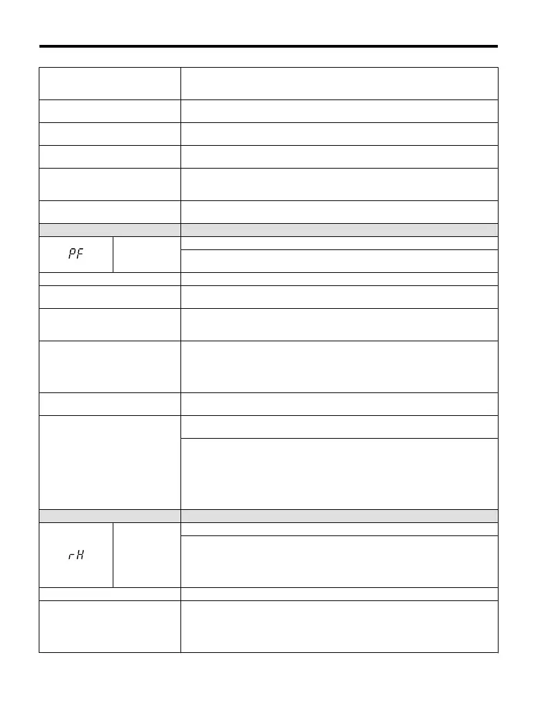
LED Operator Display Fault Name
PF
Input Phase Loss
Drive input power has an open phase or has a large imbalance of voltage between
phases. Detected when L8-05 = 1 (enabled).
Cause Possible Solution
There is phase loss in the drive input
power.
• Check for wiring errors in the main circuit drive input power.
• Correct the wiring.
There is loose wiring in the drive
input power terminals.
• Ensure the terminals are tightened properly.
• Apply the tightening torque specified in this manual to fasten the terminals.
Refer to Wire Gauges and Tightening Torque on page 50
There is excessive fluctuation in the
drive input power voltage.
• Check the voltage from the drive input power.
• Review the possible solutions for stabilizing the drive input power.
• Disable Input Phase Loss Detection (L8-05 = “0”). PF is detected if DC bus
ripple is too high.
If it is disabled, there is no fault but the ripple is still too high,
thereby the capacitors are stressed more and lose lifetime.
There is poor balance between
voltage phases.
• Stabilize drive input power or disable phase loss detection.
The main circuit capacitors are
worn.
• Check the maintenance time for the capacitors (U4-05).
• Replace the drive if U4-05 is greater than 90%.
• Check for anything wrong with the drive input power.
• If nothing is wrong with the drive input power, try the following solutions if
the alarm continues:
• Disable Input Phase Loss Protection selection (L8-05 = “0”). PF is detected if
DC bus ripple is
too high. If it is disabled, there is no fault but the ripple is still
too high, thereby the capacitors are stressed more and lose lifetime.
• Replace the drive.
LED Operator Display Fault Name
rH
Braking Resistor Overheat
Braking resistor protection was triggered.
Fault detection is enabled when L8-01 = 1 (disabled as a default).
Note: The magnitude of the
braking load trips the braking resistor overheat alarm,
NOT the surface temperature. Using the braking resistor more frequently than its
rating trips the alarm even when the braking resistor surface is not very hot.
Cause Possible Solution
Deceleration time is too short and
excessive regenerative energy is
flowing back into the drive.
• Check the load, deceleration time and speed.
• Reduce the load.
• Increase the acceleration and deceleration times (C1-01 through C1-04).
• Replace the braking
option with a larger device that can handle the power that
is discharged.
5.4 Fault Detection
132
YASKAWA ELECTRIC TOEP C710606 25B YASKAWA AC Drive J1000 Installation & Start-Up Manual
2/6/2008-14:44

 Loading...


