Excessive braking inertia.
Recalculate braking load and braking power. Then try reducing the braking load
and checking the braking resistor settings and improve braking capacity.
The proper braking resistor has not
been installed.
• Check the specifications and conditions for the braking resistor device.
• Select the optimal braking resistor.
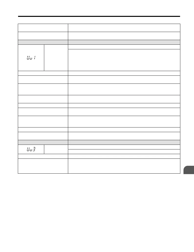
LED Operator Display Fault Name
Uv1
DC Bus Undervoltage
One of the following conditions occurred while the drive was stopped:
• Voltage in the DC bus fell below the undervoltage detection level.
• For 200 V class: approximately 190 V (160 V for single phase drives)
• For 400 V class:
approximately 380 V (350 V when E1-01 is less than 400) The
fault is output only if L2-01 = 0 or L2-01 = 1 and the DC bus voltage is under
L1-05 for longer than L2-02.
Cause Possible Solution
Input power phase loss.
• The main circuit drive input power is wired incorrectly.
• Correct the wiring.
One of the drive input power wiring
terminals is loose.
• Ensure there are no loose terminals.
• Apply the tightening torque specified in this manual to fasten the terminals.
Refer to Wire Gauges and Tightening Torque on page 50
There is a problem with the voltage
from the drive input power.
• Check the voltage.
• Correct the voltage to within range listed in drive input power specifications.
The power has been interrupted. Correct the drive input power.
Drive internal circuitry has become
worn.
• Check the maintenance time for the capacitors (U4-05).
• Replace the drive if U4-05 exceeds 90%.
The drive input power transformer
is not large enough and voltage
drops after switching on power.
Check the capacity of the drive input power transformer.
Air inside the drive is too hot. Check the drive internal temperature.
Problem with the CHARGE
indicator.
Replace the drive.
LED Operator Display Fault Name
Uv3
Undervoltage 3 (Inrush Prevention Circuit Fault)
The inrush prevention circuit has failed.
Cause Possible Solution
The contactor on the inrush
prevention circuit is damaged.
• Cycle power to the drive. Check if the fault reoccurs.
• Replace the drive if the fault continues to occur.
• Check monitor U4-06 for the
performance life of the inrush prevention circuit.
• Replace the drive if U4-06 exceeds 90%.
5.4 Fault Detection
YASKAWA ELECTRIC TOEP C710606 25B YASKAWA AC Drive J1000 Installation & Start-Up Manual
133
5
Troubleshooting
2/6/2008-14:44

 Loading...


