B C
D
A
R/L1
1
2
3
4
E
MCCB
MCCB
S/L2
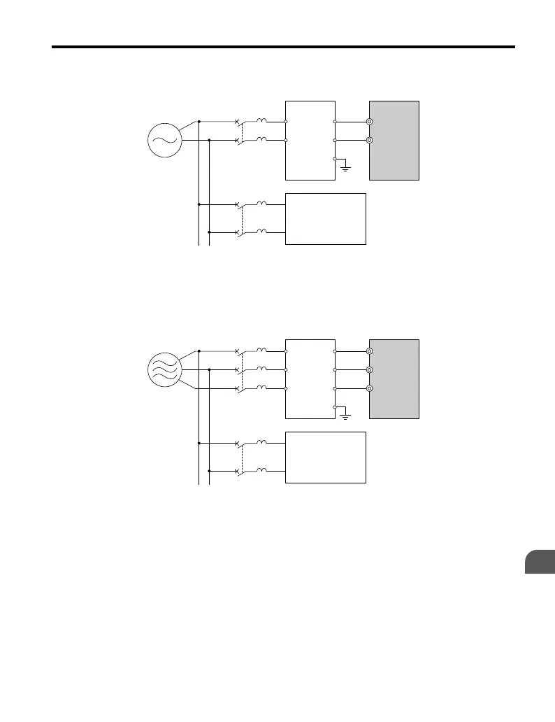
A – Power supply
B – Input-side noise filter
C – Drive
D – Other control device
Figure 7.6 Input-Side Noise Filter (Single-Phase 200 V)
C
D
A
B
R/L1
U
V
W
R
S
T
E
MCCB
MCCB
S/L2
T/L3
A – Power supply
B – Input-side noise filter
C – Drive
D – Other control device
Figure 7.7 Input-Side Noise Filter (Three-Phase 200/400 V)
n
Output-Side Noise Filter
A noise filter on the output side
of the drive reduces inductive noise and radiated noise. Figure
7.8 illustrates an example of output-side noise filter wiring.
NOTICE: Do not connect phase-advancing capacitors or LC/RC noise filters to the output circuits. Improper
application of noise filters could result in damage to the drive.
7.4 Installing Peripheral Devices
YASKAWA ELECTRIC TOEP C710606 25B YASKAWA AC Drive J1000 Installation & Start-Up Manual
175
7
Peripheral Devices &
Options
2/6/2008-14:44

 Loading...


