6.3 MEMOBUS/Modbus Communications
218 YASKAWA SIEPC71061753C GA500 Technical Manual
6.3 MEMOBUS/Modbus Communications
This section gives detailed information about the parameters, error codes and communication procedures for
MEMOBUS/Modbus communications.
◆ Configure Master/Slave
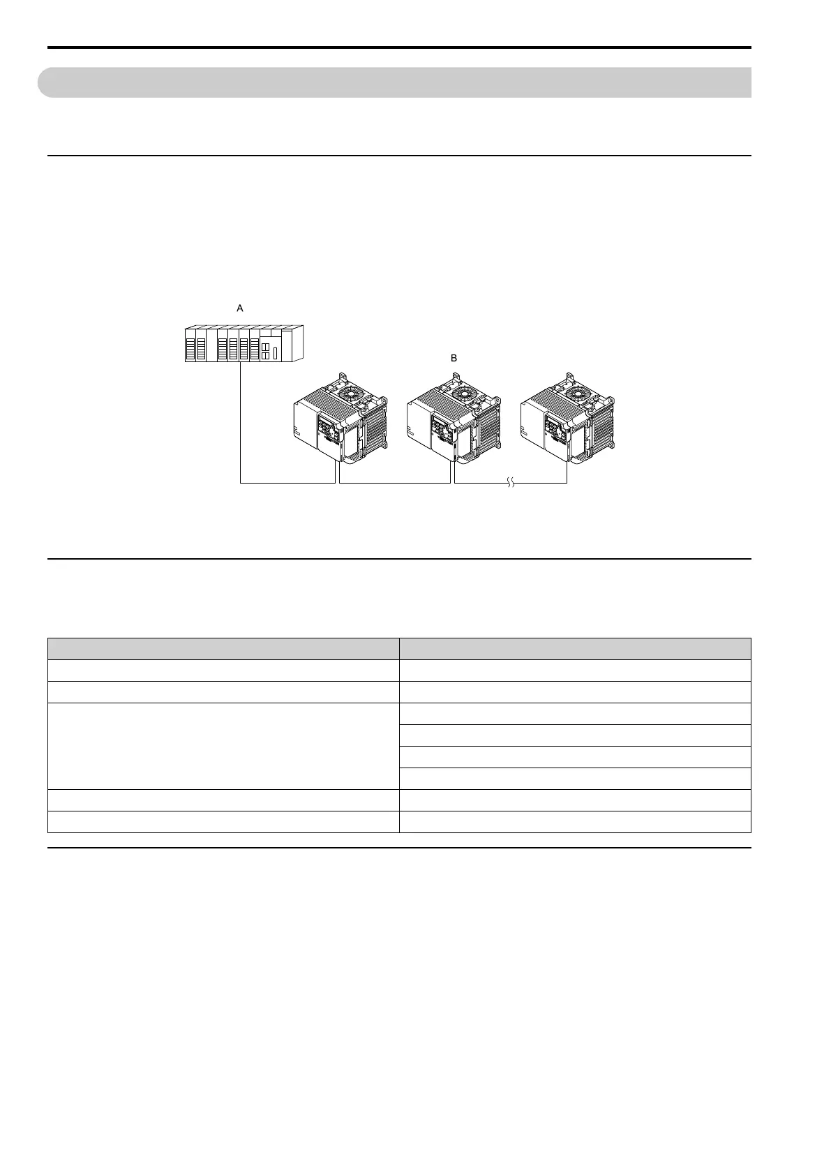
You can use the MEMOBUS/Modbus protocol for serial communication with programmable controllers (PLC).
The MEMOBUS/Modbus communication uses one master (PLC) and a maximum of 31 slave drives. Serial
communications usually starts with a signal from the master to the slave drives.
A slave drive that receives a command from the master does the specified function and then sends a response back
to the master. You must set the address number for each slave drive before you start signal communications to
make sure that the master uses the correct address numbers.
A - Master (PLC) B - Slave (drive)
Figure 6.1 PLC and Drive Connection Example
◆ Communication Specifications
Table 6.2 lists the specifications for the MEMOBUS/Modbus communications.
Table 6.2 MEMOBUS/Modbus Specifications
Item Specification
Interface RS-485
Synchronization method Asynchronous (start-stop synchronization)
Communication parameter
Communications speed:1.2, 2.4, 4.8, 9.6, 19.2, 38.4, 57.6, 76.8, 115.2 kbps
Data length: 8 bit (fixed)
Parity: even, odd, none
Stop bit 1 bit (fixed)
Communication protocol MEMOBUS/Modbus standard (RTU mode only)
Number of possible units to connect Maximum: 31 units
◆ Communication with the PLC
This section gives information about the settings for the termination resistor and how to connect to MEMOBUS/
Modbus communications. MEMOBUS/Modbus communications uses an RS-485 interface (2-wire sequence).
■ Connect Communications Cable
Use this procedure to start communication between the PLC and drive.

 Loading...


