12.8 H: Terminal Function Selection
684 YASKAWA SIEPC71061753C GA500 Technical Manual
■ H5-25: Function 5A Register 1 Selection
No.
(Hex.)
Name Description
Default
(Range)
H5-25
(1589)
RUN
Function 5A Register 1
Selection
Returns the contents of the specified MEMOBUS/Modbus communications register when
responding to the master device.
0044H (U1-05)
(0000H - FFFFH)
Note:
Refer to Writing to More than One Holding Register/Reading the Indicated Register on page 225 for more information.
■ H5-26: Function 5A Register 2 Selection
No.
(Hex.)
Name Description
Default
(Range)
H5-26
(158A)
RUN
Function 5A Register 2
Selection
Returns the contents of the specified MEMOBUS/Modbus communications register when
responding to the master device.
0045H (U1-06)
(0000H - FFFFH)
Note:
Refer to Writing to More than One Holding Register/Reading the Indicated Register on page 225 for more information.
■ H5-27: Function 5A Register 3 Selection
No.
(Hex.)
Name Description
Default
(Range)
H5-27
(158B)
RUN
Function 5A Register 3
Selection
Returns the contents of the specified MEMOBUS/Modbus communications register when
responding to the master device.
0042H (U1-03)
(0000H - FFFFH)
Note:
Refer to Writing to More than One Holding Register/Reading the Indicated Register on page 225 for more information.
■ H5-28: Function 5A Register 4 Selection
No.
(Hex.)
Name Description
Default
(Range)
H5-28
(158C)
RUN
Function 5A Register 4
Selection
Returns the contents of the specified MEMOBUS/Modbus communications register when
responding to the master device.
0049H (U1-10)
(0000H - FFFFH)
Note:
Refer to Writing to More than One Holding Register/Reading the Indicated Register on page 225 for more information.
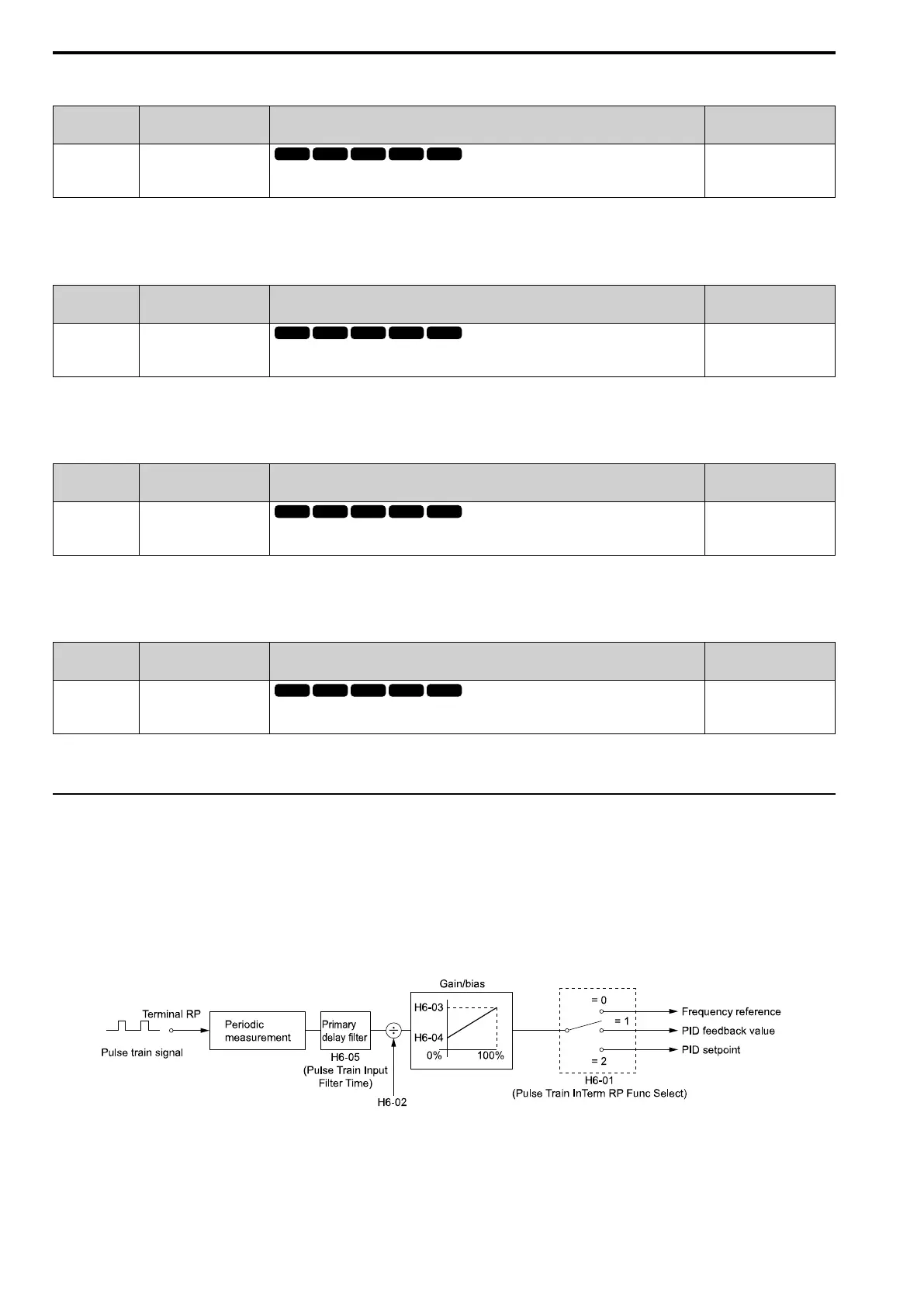
◆ H6: Pulse Train Input/Output
H6 parameters set the drive pulse train input and pulse train monitor. These parameters select input and monitor
parameters and adjust the pulse train frequency.
A pulse train signal with a maximum single pulse of 32 kHz can be input to the drive input terminal RP. You can
use the pulse train signal as the frequency reference, PID feedback value, PID setpoint value, and speed feedback
for V/f Control mode.
A pulse train signal with a maximum frequency of 32 kHz can be output from the drive output terminal MP as the
monitor value. Sinking mode and sourcing mode are supported.
Figure 12.101 Pulse Train Input Block Diagram

 Loading...


