Network Communications
6
6.3 MEMOBUS/Modbus Communications
YASKAWA SIEPC71061753C GA500 Technical Manual 225
Byte
Command Message Response Message (When Normal) Response Message (When There is a Fault)
Setting Data (Hex.) Setting Data (Hex.) Setting Data (Hex.)
6 Byte No. 04
CRC-16
Upper 10 -
7
First data
Upper 00 Lower 08 -
8 Lower 01 - -
9
Next data
Upper 17 - -
10 Lower 70 - -
11
CRC-16
Upper 6D - -
12 Lower B7 - -
Note:
The number of bytes set in the command message set the data quantity × 2 during the command message. The response message uses
the same formula.
■ Writing to More than One Holding Register/Reading the Indicated Register
The drive uses function code 5A (Hex.) to write to more than one register, then it reads the contents of four
holding registers at the same time.
The function for writing to more than one register is the same as the function for function code 10 (Hex.). You can
write to a maximum of 16 holding registers.
The four holding registers to be read from are specified in H5-25 to H5-28 [Function 5A Register x Selection].
Table 6.10 shows example messages when you write to more than one holding register or when you read more
than one command register. Table 6.10 uses this register data for the examples:
• The drive for slave 1 is set for Forward run with a frequency reference of 60.00 Hz.
• The setting in H5-25 to H5-28 and the data in the specified holding registers are as follows.
– H5-25 = 0044H: U1-05 [Motor Speed] = 60.00 Hz (6000 = 1770H)
– H5-26 = 0045H: U1-06 [Output Voltage Ref] = 200.0 V (2000 = 07D0H)
– H5-27 = 0042H: U1-03 [Output Current] = 50% of drive rated current (100% = 8192, 50% = 4096 = 1000H)
– H5-28 = 0049H: U1-10 [Input Terminal Status] = 00H
When you rewrite the parameter value with the write command through the H5-11 [Comm ENTER Command
Mode] setting, you must use the Enter command to save and enable the contents of the changes. Refer to H5-11:
Comm ENTER Command Mode on page 682 and Enter Command on page 227 for more information.
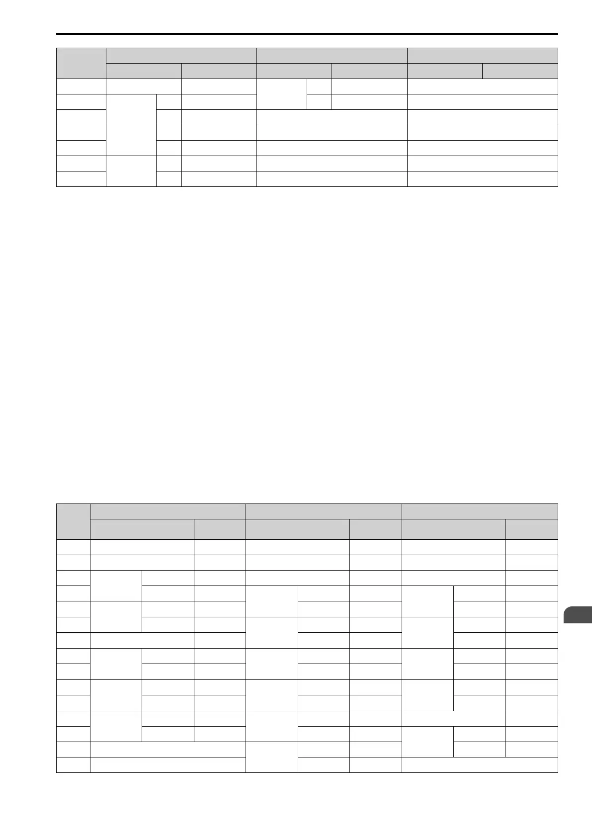
Table 6.10 Message Example When Writing to More than One Holding Register/Reading the Indicated Register
Byte
Command Message Response Message (When Normal) Response Message (When There is a Fault)
Setting Data
(Hex.)
Setting Data
(Hex.)
Setting Data
(Hex.)
0 Slave address 01 Slave address
01 Slave address 01
1 Function code 5A Function code
5A
Function code DA
2
Starting No.
Upper 00 Register status 0F Register status 0F
3 Lower 01
Data in holding
register 1
selected with
H5-25
Upper 17
Data in holding
register 1
selected with
H5-25
Upper 17
4
Data Quantity
Upper 00 Lower 70 Lower 70
5 Lower 02
Data in holding
register 2
selected with
H5-26
Upper 07
Data in holding
register 2
selected with
H5-26
Upper 07
6 Byte No. 04 Lower D0 Lower D0
7
First data
Upper 00
Data in holding
register 3
selected with
H5-27
Upper 10
Data in holding
register 3
selected with
H5-27
Upper 10
8 Lower 01 Lower 00 Lower 00
9
Next data
Upper 17
Data in holding
register 4
selected with
H5-28
Upper 00
Data in holding
register 4
selected with
H5-28
Upper 00
10 Lower 70 Lower 00 Lower 00
11
CRC-16
Upper 4F
Starting No.
Upper 00 Error code 02
12 Lower 43 Lower 01
CRC-16
Upper E9
13 -
Data Quantity
Upper 00 Lower 6C
14 - Lower 02 -

 Loading...


