Electrical Installation
3
3.3 Main Circuit Wiring
YASKAWA SIEPC71061753C GA500 Technical Manual 65
3.3 Main Circuit Wiring
This section gives information about the functions, specifications, and procedures necessary to safely and
correctly wire the main circuit in the drive.
NOTICE: Damage to Equipment. Do not energize and de-energize the drive more frequently than one time each 30 minutes. If
you frequently energize and de-energize the drive, it can cause drive failure.
Note:
Soldered wire connections can become loose over time and cause unsatisfactory drive performance.
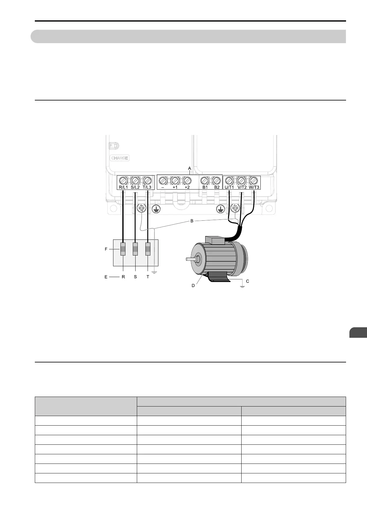
◆ Motor and Main Circuit Connections
WARNING! Electrical Shock Hazard. Do not connect terminals R/L1, S/L2, T/L3, L/L1, N/L2, U/T1, V/T2, W/T3, -, +1, +2, B1, or
B2 to the ground terminal. If you connect these terminals to earth ground, it can cause damage to the drive or serious injury or
death.
Note:
The locations of terminals are different for different drive models.
A - DC bus terminal
B - Connect to the drive ground terminal.
C - Ground the motor case.
D - Three-Phase Motor
E - Use terminals R/L1, S/L2, and T/L3 for three-
phase power supply input. Use terminals L/L1
and N/L2 for single-phase power supply input.
F - Input Protection (Fuses or Circuit Breakers)
Figure 3.2 Wiring the Main Circuit and Motor
◆ Configuration of Main Circuit Terminal Block
Use Table 3.1 to find the correct main circuit terminal block figure for your drive.
Table 3.1 Configuration of Main Circuit Terminal Block
Model
Figure
No internal EMC filter Built-in EMC Filter
B001 - B004 Figure 3.3 Figure 3.4
2001 - 2006 Figure 3.5 Figure 3.6
B006, B010 Figure 3.7 Figure 3.8
2008 - 2012, 4001 - 4009 Figure 3.9 Figure 3.10
B012 Figure 3.11 Figure 3.12
2018 - 2021, 4012 Figure 3.13 Figure 3.14
B018 Figure 3.15 -

 Loading...


