Parameter Details
12
12.3 b: Application
YASKAWA SIEPC71061753C GA500 Technical Manual 509
Note:
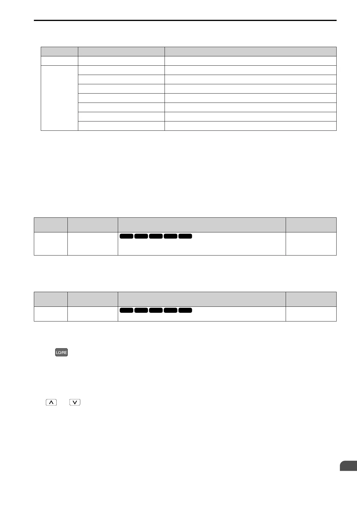
Refer to this table for Drive Mode and Programming Mode functions.
Mode Keypad Screen Function
Drive Mode Monitors
Sets monitor display.
Programming Mode
Parameters
Changes parameter settings.
User Custom Parameters
Shows the User Parameters.
Parameter Backup/Restore
Saves parameters to the keypad as backup.
Modified Parameters/Fault Log
Shows modified parameters and fault history.
Auto-Tuning
Auto-Tunes the drive.
Initial Setup Screen
Changes initial settings.
Diagnostic Tools
Sets data logs and backlight.
0 : Disregard RUN while Programming
The drive does not accept the Run command when setting the parameters in the Programming Mode.
1 : Accept RUN while Programming
The drive accepts a Run command entered from an external source when setting the parameters in Programming
Mode.
2 : Allow Programming Only at Stop
The drive does not allow the user to enter the Programming Mode while the drive is operating. The keypad does
not display the Programming Mode while the drive is operating.
■ b1-14: Phase Order Selection
No.
(Hex.)
Name Description
Default
(Range)
b1-14
(01C3)
Phase Order Selection
Sets the phase order for output terminals U/T1, V/T2, and W/T3. This parameter can align the
Forward Run command from the drive and the forward direction of the motor without changing
wiring.
0
(0, 1)
0 : Standard
1 : Switch Phase Order
■ b1-15: Frequency Reference Selection 2
No.
(Hex.)
Name Description
Default
(Range)
b1-15
(01C4)
Frequency Reference
Selection 2
Sets the input method for frequency reference 2.
0
(0 - 4)
This parameter is enabled when H1-xx = 2 [MFDI Function Selection = External Reference 1/2 Selection] is
activated.
Note:
• Push on the keypad to set the input mode to LOCAL and use the keypad to enter the frequency reference.
• If the frequency reference is 0 Hz or less than or equal to the value set in E1-09 [Minimum Output Frequency] and the drive receives
the Run command, the RUN LED on the keypad will flash. Examine the setting for the frequency reference input and enter a value
more than or equal to E1-09.
0 : Keypad
Use the keypad to enter the frequency reference.
Use and on the keypad to change the frequency reference.
1 : Analog Input
Use MFAI terminals A1 and A2 to input an analog frequency reference with a voltage or current input signal.
• Voltage Input
Refer to Table 12.25 to use a voltage signal input to one of the MFAI terminals.

 Loading...


