Parameter Details
12
12.8 H: Terminal Function Selection
YASKAWA SIEPC71061753C GA500 Technical Manual 647
Setting Value Function Reference
37 During Frequency Output 664
38 Drive Enabled 664
39 Watt Hour Pulse Output 664
3C LOCAL Control Selected 664
3D During Speed Search 665
3E PID Feedback Low 665
3F PID Feedback High 665
4A During KEB Ride-Thru 665
4B During Short Circuit Braking 665
4C During Fast Stop 665
4D oH Pre-Alarm Time Limit 665
4E Braking Transistor Fault (rr) 666
4F Braking Resistor Overheat (rH) 666
Setting Value Function Reference
61 Pole Position Detection Complete 666
62 Modbus Reg 1 Status Satisfied 666
63 Modbus Reg 2 Status Satisfied 666
66 Comparator1 666
67 Comparator2 667
69 External Power 24V Supply 667
6A Data Logger Error 667
90 to 92 DWEZ Digital Output 1 to 3 667
100 to 192
Inverse output of 0 to 92
Sets an inverse output of the function for
the MFDO. Put a 1 at the front of the
function setting to set inverse output. For
example, set 138 for inverse output of 38
[Drive Enabled].
667
*1 Inverse output is not available.
■ Extended MFDO1 to MFDO3 Function Selection
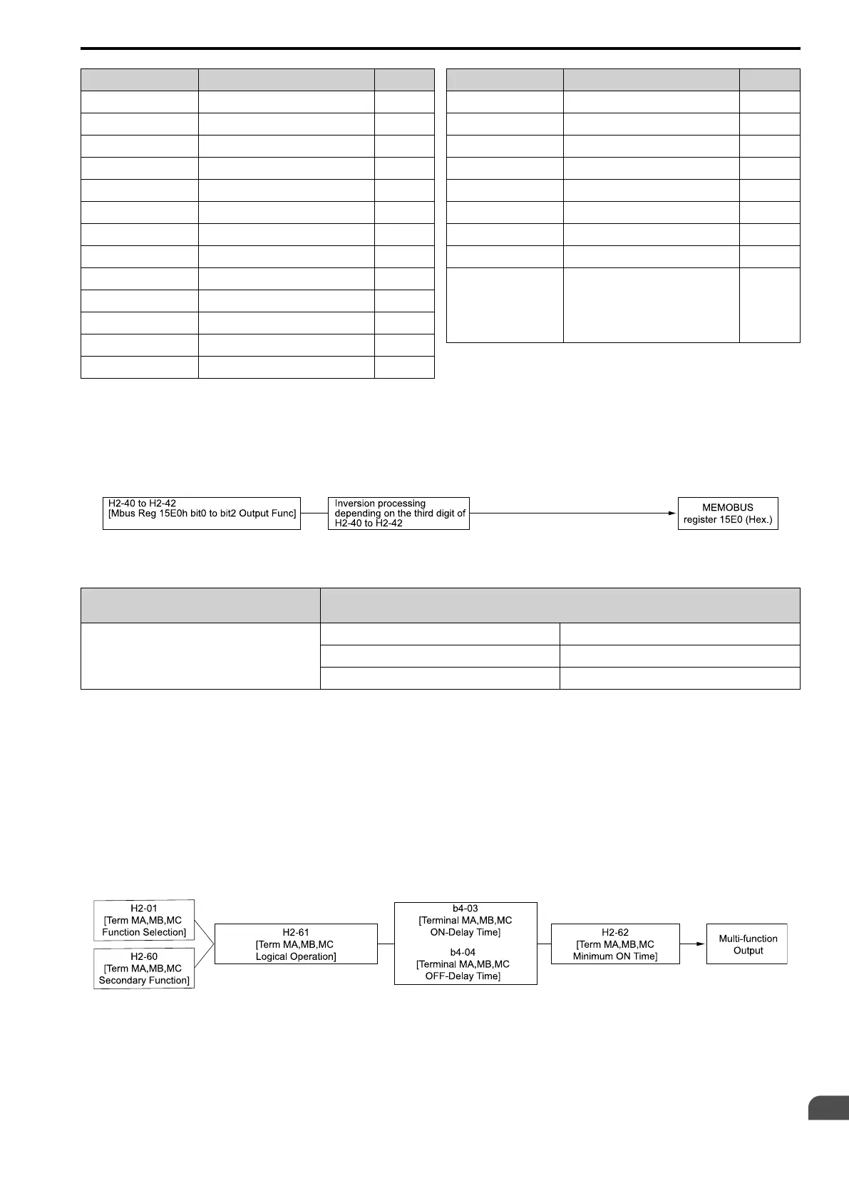
You can set MFDO functions to bit 0 to bit 2 [MEMOBUS MFDO1 to 3] of MEMOBUS register 15E0 (Hex.).
Use H2-40 to H2-42 [Mbus Reg 15E0h bit0 to bit2 Output Func] to select the function.
Figure 12.74 Functional Block Diagram of MEMOBUS Multi-function Output
Table 12.62 MEMOBUS MFDO Registers
Register number
(Hex.)
Name
15E0
bit0 MEMOBUS MFDO 1
bit1 MEMOBUS MFDO 2
bit2 MEMOBUS MFDO 3
Note:
• Refer to MFDO Setting Values on page 655 for more information about MFDO setting values.
• When you do not set functions to H2-40 to H2-42, set them to F.
■ Output of Logical Operation Results of MFDO
This enables the logical operation results of two MFDOs to be output to one MFDO terminal.
Use H2-60, H2-63, and H2-66 [Term MA,MB,MC Secondary Function, Terminal P1 Secondary Function, and
Terminal P2 Secondary Function] to set the function of the output signal for which you will perform logical
operations.
Use H2-61, H2-64, and H2-67 [Term MA,MB,MC Logical Operation, Terminal P1 Logical Operation, and
Terminal P2 Logical Operation] to set the logical operation.
Figure 12.75 Functional Block Diagram of Logical Operation Output for MFDO 1

 Loading...


