12.9 L: Protection Functions
692 YASKAWA SIEPC71061753C GA500 Technical Manual
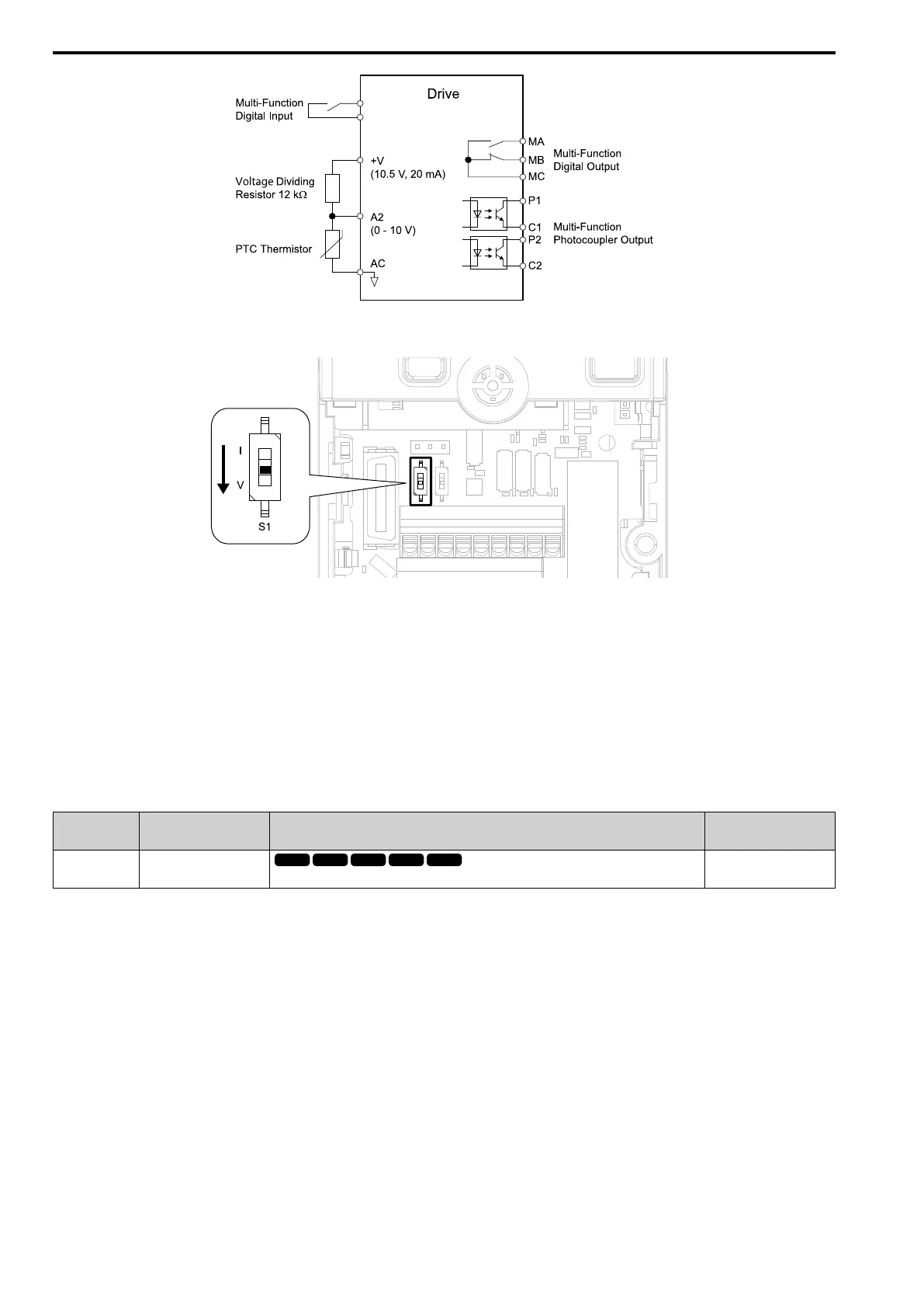
Figure 12.108 Connect Motor to PTC Thermistor Input
2. Set drive DIP switch S1 to V (voltage).
Figure 12.109 Settings for DIP Switches
3. Set these MFAI terminals:
• H3-09 = 0 [Terminal A2 Signal Level Select = 0-10V (LowLim=0)].
• H3-10 = E [Terminal A2 Function Selection = Motor Temperature (PTC input)].
4. Set these L1 parameters:
• L1-03 [Motor Thermistor oH Alarm Select]
• L1-04 [Motor Thermistor oH Fault Select]
• L1-05 [Motor Thermistor Filter Time]
■ L1-01: Motor Overload (oL1) Protection
No.
(Hex.)
Name Description
Default
(Range)
L1-01
(0480)
Motor Overload (oL1)
Protection
Sets the motor overload protection with electronic thermal protectors.
Determined by A1-02
(0 - 6)
This parameter enables and disables the motor overload protection with electronic thermal protectors.
The cooling capability of the motor changes when the speed control range of the motor changes. Use an electronic
thermal protector that aligns with the permitted load characteristics of the motor to select motor protection.
The electronic thermal protector of the drive uses these items to calculate motor overload tolerance and supply
overload protection for the motor:
• Output current
• Output frequency
• Motor thermal characteristics
• Time characteristics
If the drive detects motor overload, the drive will trigger an oL1 [Motor Overload] and stop drive output.
Set H2-01 = 1F [Term MA/MB-MC Function Selection = Motor Overload Alarm (oL1)] to set a motor overload
alarm. If the motor overload level is more than 90% of the oL1 detection level, the output terminal activates and
triggers an overload alarm.
0 : Disabled

 Loading...


