120 YASKAWA ELECTRIC TOEP C710687 02B FSDrive-MV1000 Instructions
4.4 Start-Up Flowcharts
4.4 Start-Up Flowcharts
The flowcharts in this section summarize basic steps required to start the drive. Use the flowcharts to determine the most
appropriate start-up method for a given application. The charts are quick references to help familiarize the user with
startup procedures.
u Flowchart A: Basic Start-Up and Motor Tuning
Flowchart A describes a basic start-up sequence that varies slightly depending on the application. Use drive default
parameter settings in simple applications that do not require high precision.
Figure 4. 8
Figure 4.8 Basic Start-Up
Flowchart Subchart Objective Page
A – Basic start-up procedure and motor tuning 120
–
A-1 Parallel operation of multiple motors by V/f control 121
A-2
High-performance operation using Open Loop Vector (OLV) or Closed Loop Vector (CLV)
induction motor control
122
START
Install and wire the drive as explained in Chapters 1, 2, and 3.
Measure the insulation of the transformer.
Turn on the control power.
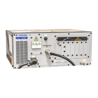
Check from this display (control board) whether the status is normal.
Set the control mode in parameter A1-02.
To
Flowchart A-1
Control Mode
A1-02 =
To
Flowchart A-2
Set the basic parameters
b1-01/02 for frequency reference and Run command source selection
H1-, H2-, H3-, H4- for I/O terminal setting
d1- for multi-step speed references if used
Enter the settings for acceleration/deceleration and S-curve characteristics at C1-
and C2-.
Fine tune parameters. Adjust application settings if necessary.
Check the machine operation and verify parameter settings.
Drive is ready to run the application.
From Flowchart A-1, A-2
0: V/f
2: OLV
3: CLV

 Loading...


