2.2 Mechanical Installation
YASKAWA ELECTRIC TOEP C710687 02B FSDrive-MV1000 Instructions 57
u Side-by-Side Installation
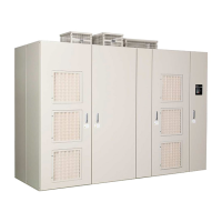
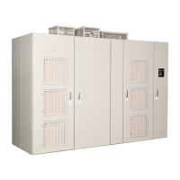
“Side-by-side” installation means a configuration in which a transformer panel, Power Cell panel and control panel
separate when delivered are placed side-by-side, and are wired together.
The following models are installed side by side in a block construction (Table 2. 10).
2 kV class: 700 to 2750 HP
3 kVclass: 1150 to 3700 kVA (200A to 650A)
4 kV class: 1250 to 5000 HP
6 kV class: All models
11 kV class: All models
Note: Models other than those indicated above are delivered with the transformer panel, Power Cell panel and control panel integrated
within a single frame.
On these models, eight holes are provided each on the transformer panel frame and Power Cell panel frame (refer to the
figure below).
Use M10
× 30L bolts, washers, S-washers, and nuts to join the sections.
Figure 2.21
Figure 2.21 Mounting Holes for Side-by-Side Installation
When installing side by side a drive in a block construction, ensure that the specifications indicated in the table below are
satisfied.
Table 2.16 Side-by-Side Configuration
NOTICE: When bolting frames between panel to each other, make secure connections by using the tightening torque indicated in this
manual. Any space between two frames may cause a leakage of cooling air, resulting in drive failure.
Category Specifications
Bolts between Panel Tightening torque of M10 bolts provided as accessories: 18 to 23 Nxm (lb.in.)
Wiring between
Panel
Perform the following wiring between panels.
• Main circuit wiring
• Grounding bus bars
• Cooling fan wiring
• Resistance temperature detector: PT100
• Thermal switch
• Fiber optic cable
Installation
Accuracy of Drive
Panels
Use a measuring instrument such as a theodolite to measure the levelness on the installation base at 1-meter
intervals, and adjust to achieve a levelness error of within ±2 mm.
Transformer panel frame
Arrows: Positions of bolts
Power Cell panel frame

 Loading...


