1.4 Component Names and Configurations
YASKAWA ELECTRIC TOEP C710687 02B FSDrive-MV1000 Instructions 35
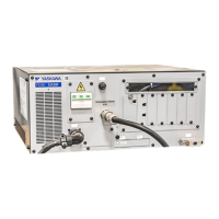
u Digital Operator, Communications Connector, and Internal Layout for Control Panel
Figure 1.13
Figure 1.13 Digital Operator and Communications Connector for Control Panel
Figure 1.14
Figure 1.14 Internal Layout for Control Panel
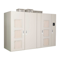
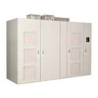
The drive is composed of the following three elements:
• Transformer panel
• Power Cell panel
• Control panel
Note: A digital operator for reading and writing parameter settings and monitoring status and faults, and a USB connector for
DriveWizard Plus MV communications are provided on the control panel door. Refer to Using the Digital Operator on page 109
for details on the names and functions of the digital operator controls.
A – Serial communications connector
for drive
D – Selector switch
B – USB connector E – Digital operator
C – Serial communications connector
for PLC option
A – Control board G – Noise filter
B – Relay board H – Current sensor board (option)
C – Contactor and relay I – DC power supply
D – Relay board (option) J – Circuit breaker
E – Option board K – Pull-out handle
F – Fan Fault Detection board
B
C
D
E
%$
%$ %$
%$
A
B
C
CD
G
H
I
G
E F
K
J
Cross section Front view

 Loading...


