3.3 Terminals
YASKAWA ELECTRIC TOEP C710687 02B FSDrive-MV1000 Instructions 83
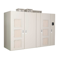
Figure 3.8
Figure 3.8 Terminal Locations (Drive: 4 kV Class, 1250 HP)
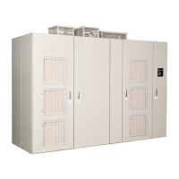
Figure 3.9
Figure 3.9 Terminal Locations (Drive: 6 kV Class, 1600 kVA)
A – Cooling fan D – Main circuit output terminals U, V, and W
B – Power Cell E – Grounding terminal EA
C – Control circuit terminals
Grounding terminal ED
F – Main circuit input terminals R, S, and T
A – Cooling fan D – Main circuit output terminals U, V, and W
B – Power Cell E – Grounding terminal EA
C – Control circuit terminals
Grounding terminal ED
F – Main circuit input terminals R, S, and T
Transformer panel Power Cell panel Control panel
A
B
C
D
UV W
F
T
R
S
E
Front view
Left side view
Right side view
%$
(.
$0.$0.
$0.$0.
%$
%$
$0.$0.
$0.$0.
%$
$0.$0.
$0.$0.
$0.$0.
$0.$0.
ᵈᗧᵈᗧ
ᵈᗧᵈᗧ
%#76+10
2NGCUGNCRDCPFDGVYGGPRCPGNHNCOG
%#76+10
DGVYGGPRCPGNHNCOGCPFVJKUWPKV
2NGCUGFQPQVECVEJVJGHKPIGT
JQNGCPFJCPFNGCVVTCPURQTV
ޓࡄࡀ࡞ࡈ㧙ࡓߣᧄ࡙࠾࠶࠻ߣߩ㑆ߢᜰࠍ߹ߥࠃ߁ߦ
ޓャㅍᤨߩࡂࡦ࠼࡞ᛮߌ㒐ᱛ↪ߦࡄࡀ࡞ࡈ㧙ࡓⓣߣࡂࡦ࠼࡞
ߩ㑆ߦ⚿᧤ࡃࡦ࠼╬ࠍᏎ߈ઃߌߡߐޕ
%%
%%
66
66
66
66
%%
%%
66
66
66
66
%%
%%
66
66
66
66
'&'&
$0.$0.
$0.$0.
5%5%
4%4%
'&'&
'&'&
'&'&
'&'&
'&'&
'&'&
'&'&
'&'&
'&'&
'&'&
..
..
..
..
..
..
..
..
..
$0.$0.
(.
'&'&
$0.$0.
$0.$0.
5%5%
4%4%
'&'&
'&'&
'&'&
'&'&
'&'&
'&'&
'&'&
'&'&
'&'&
'&'&
..
..
..
..
..
..
..
..
..
$0.$0.
㨀㧛㨀㧛 㧿㧛㧿㧛
㨁㧝㨁㧝
㧱㧭㧱㧭
㨂㧝㨂㧝
㧾㧛㧾㧛
㧱㧭㧱㧭
㨃㧝㨃㧝
㧱㧭㧱㧭
A
B
C
D
F
E
S
T
R
V
U
W
Front view
Left side view
Right side view
Transformer panel Power Cell panel Control panel

 Loading...


