3.4 Cable Routing
YASKAWA ELECTRIC TOEP C710687 02B FSDrive-MV1000 Instructions 87
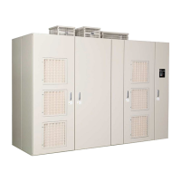
Figure 3.14
Figure 3.14 Cable Routing (Drive: 6 kV Class, 1600 kVA)
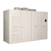
Figure 3.15
Figure 3.15 Cable Routing (Drive: 11 kV Class, 2650 kVA)
A – Control circuit terminal E – Control circuit cable
B – Output side main circuit
terminals U, V, and W
F – Cable bracket
C – Cable bracket clamp G – Input side main circuit cable
D – Output side main circuit cable H – Input side main circuit terminals
R, S, and T
A – Control circuit terminal E – Control circuit cable
B – Output side main circuit terminals
U, V, and W
F – Cable bracket
C – Cable bracket clamp G – Input side main circuit cable
D – Output side main circuit cable H – Input side main circuit terminals
R, S, and T
Transformer panel
Left side view
A
Power Cell panel
B
C
VU W
Front view
Right side view
D
D
G
G
TS
R
E
F
F
H
C
Control panel
A
B
C
D
D
G
G
E
F
F
H
C
࠻
࠻
࠻
࠻
࠻
࠻
࠻
࠻
࠻
࠻
࠰
ࠈ
࠰
ࠈ
ࡕࡕࡕࡕࡕ
㨀
㧿
㧾
㨂
㨃
㨁
ࠕ
ࠕ
'&
5%
4%
'&
'&
'&
'&
'&
'&
'&
'&
'&
'&
.
.
.
.
.
.
.
.
.
%$
%$ %$
%$
ᵈᗧ
%#76+10
ᵈᗧ
%#76+10
ᵈᗧ
%#76+10
ᵈᗧ
%#76+10
ᵈᗧ
%#76+10
ᵈᗧ
%#76+10
ࠕ
࠰
࠻
࠻
࠻
ࠕ
࠻
࠻
࠻
࠻
ࠈ
࠰
ࡕ
ࠗ
Transformer panel
Left side view
Power Cell panel
Front view
Right side view
Control panel

 Loading...


