d1-04
d1-05
d1-06
d1-07
d1-17
d1-12
d1-13
d1-14
d1-15
d1-16
ON
ON
ON
ON
ON
ON
ON
ON
ON
ON
ON
ON
ON
ON
ON
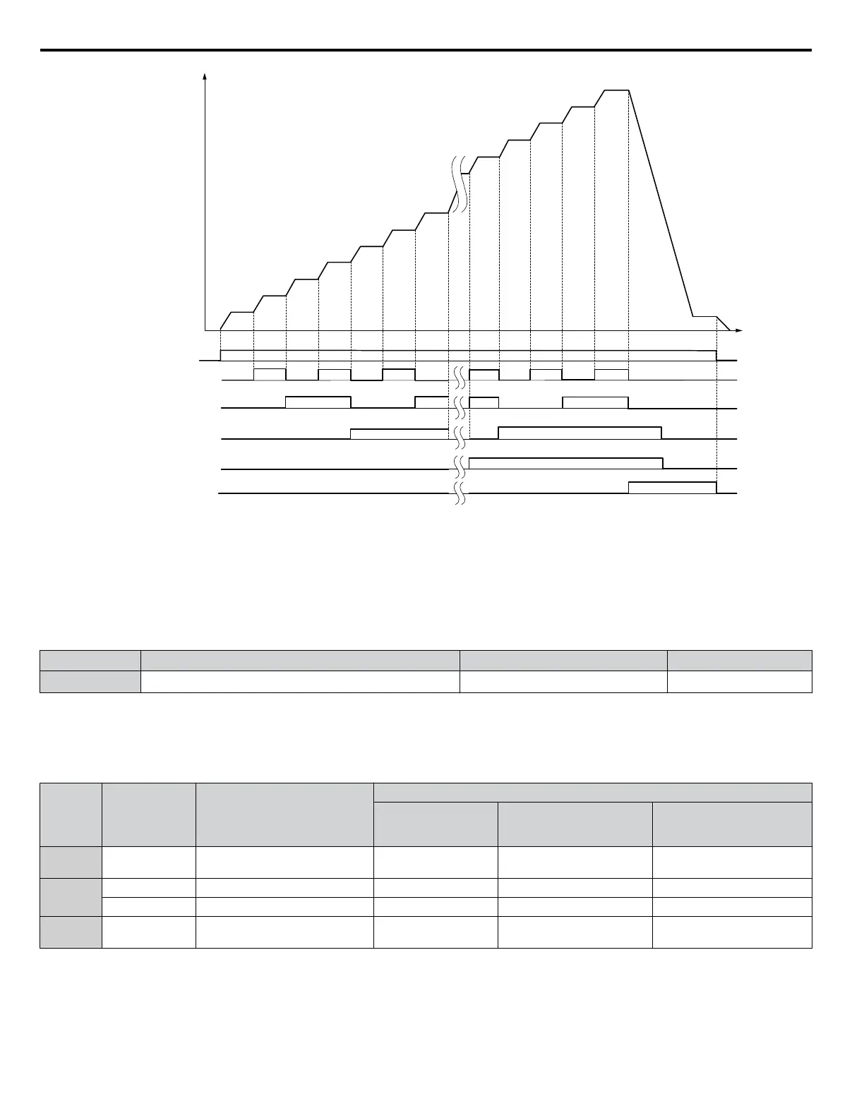
FWD (REV) Run/Stop
Multi-step Speed Ref. 2
Multi-step Speed Ref. 3
Jog Reference
Time
Multi-step Speed Ref. 1
Multi-step Speed Ref. 4
Frequency
reference
d1-01
(A1)
d1-02
(A2)
d1-03
(A3)
Figure 4.17 Preset Reference Timing Diagram
n
E1-01: Input Voltage Setting
Adjusts the levels of some protective features of the drive (overvoltage, Stall Prevention, etc.). Set this parameter to the nominal
voltage of the AC power supply.
NOTICE:
Set parameter E1-01 to match the input voltage of the drive. Drive input voltage (not motor voltage) must be set in E1-01 for the
protective features to function properly. Failure to set the correct drive input voltage will result in improper drive operation.
No. Parameter Name Setting Range Default
E1-01 Input Voltage Setting
155 to 255 V
<1>
230 V
<1>
<1> Values shown are specific to 200 V class drives. Double the value for 400 V class drives. Multiply the value by 2.875 for 600 V class drives.
E1-01 Related Values
The input voltage setting determines the overvoltage and undervoltage detection levels, the operation levels of the braking
transistor, the KEB function, and the overvoltage suppression function.
Voltage
Setting Value of
E1-01
ov Detection Level/Dynamic
Braking Transistor Detection
Level
<1>
(rr Detection Level)
(Approximate Values)
Uv Detection Level
(L2-05)
Desired DC Bus Voltage
during KEB (L2-11)
ov Suppression /
Stall Prevention Level
(L3-17)
200 V
Class
All settings 410 V / 394 V 190 V 260 V 375 V
400 V
Class
setting ≥ 400 V
820 V / 788 V 380 V 500 V 750 V
setting < 400 V 820 V / 788 V 350 V 460 V 750 V
600 V
Class
All settings 1178 V / 1132 V 475 V 635 V 930 V
<1> The braking transistor operation levels are valid for the drive internal braking transistor. When using a CDBR braking unit, refer to instruction
manual TOBPC72060000 or TOBPC72060001.
4.6 Basic Drive Setup Adjustments
102
YASKAWA ELECTRIC TOEP YAIP1U 01B YASKAWA AC Drive - P1000 Quick Start Guide

 Loading...


