3.6 Main Circuit Wiring
This section describes the functions, specifications, and procedures required to safely and properly wire the main circuit in
the drive.
NOTICE:
Do not solder the ends of wire connections to the drive. Soldered wiring connections can loosen over time. Improper wiring practices
could result in drive malfunction due to loose terminal connections.
NOTICE:
Do not switch the drive input to start or stop the motor. Frequently switching the drive on and off shortens the life of the DC bus
charge circuit and the DC bus capacitors, and can cause premature drive failures. For the full performance life, refrain from switching the
drive on and off more than once every 30 minutes.
Refer to Input Fuse Installation on page 248 for details on fuse selection.
u
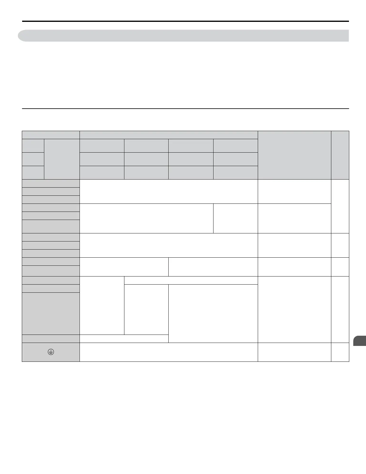
Main Circuit Terminal Functions
Table 3.1 Main Circuit Terminal Functions
Terminal Type
Function Page
200 V
Class
Drive Model
2A0004 to
2A0081
2A0110, 2A0138
2A0169 to
2A0415
–
400 V
Class
4A0002 to
4A0044
4A0058, 4A0072
4A0088 to
4A0675
4A0930, 4A1200
600 V
Class
5A0003 to
5A0032
5A0041, 5A0052
5A0062 to
5A0242
–
R/L1
Main circuit power supply input Connects line power to the drive
43
S/L2
T/L3
R1-L11
Not available
Main circuit power
supply input
Connects line power to the drive
Remove the shorting bars
connecting R/L1-R1/L11, S/L2-
S1/L21, T/L3-T1/L31 when
using 12-phase rectification.
S1-L21
T1-L31
U/T1
Drive output Connects to the motor 43V/T2
W/T3
B1
Braking resistor Not available
Available for connecting a
braking resistor or a braking
resistor unit option
–
B2
⊕2 • DC link choke
connection
(⊕1, ⊕2)
(remove the
shorting bar
between
⊕1 and ⊕2)
• DC power
supply input
(⊕1, ⊖)
Not available
For connecting:
• the drive to a DC power supply
• dynamic braking options
• a DC link choke
–
⊕1
DC power supply
input
(⊕1, ⊖)
• DC power supply input (⊕1, ⊖)
• Braking unit connection (⊕3, ⊖)
⊖
⊕3
Not available
For 200 V class: 100 Ω or less
For 400 V class: 10 Ω or less
For 600 V class: 10 Ω or less
Grounding terminal 64
Note: Use terminals B1 and ⊖ when installing a CDBR-type braking unit on drives with built-in braking transistors (Models 2A0004 to 2A0138,
4A0002 to 4A0072, and 5A0003 to 5A0052).
Wiring Fuses for Models 4A0930 and 4A1200
NOTICE:
If a fuse is blown or an Ground Fault Circuit Interrupter (GFCI) is tripped, check the wiring and the selection of peripheral devices
to identify the cause. Contact Yaskawa before restarting the drive or the peripheral devices if the cause cannot be identified.
Install a fuse on the input side to protect drive wiring and prevent other secondary damage. Wire the fuse so that leakage
current in the upper controller power supply will trigger the fuse and shut off the power supply.
Select the appropriate fuse from Table 3.2.
3.6 Main Circuit Wiring
YASKAWA ELECTRIC TOEP YAIP1U 01B YASKAWA AC Drive - P1000 Quick Start Guide
55
3
Electrical Installation