u
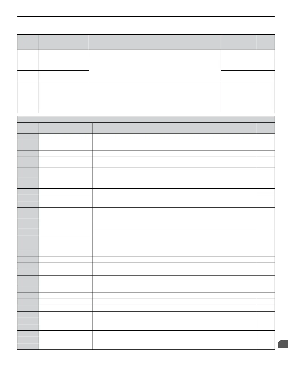
H2: Multi-Function Digital Outputs
No.
(Addr.
Hex)
Name Description Values Page
H2-01
(40B)
Terminal M1-M2 function
selection (relay)
Refer to H2 Multi-Function Digital Output Settings on pages 205 to 206 for
descriptions of setting values.
Default: 0
Range: 0 to 192
108
H2-02
(40C)
Terminal M3-M4 function
selection (relay)
Default: 1
Range: 0 to 192
108
H2-03
(40D)
Terminal MD-ME-MF
Function Selection
Default: 2
Range: 0 to 192
108
H2-06
(437)
Watt Hour Output Unit
Selection
Outputs a 200 ms pulse signal when the watt-hour counter increases by the
units selected.
0: 0.1 kWh units
1: 1 kWh units
2: 10 kWh units
3: 100 kWh units
4: 1000 kWh units
Default: 0
Range: 0 to 4
–
H2 Multi-Function Digital Output Settings
H2-oo
Setting
Function Description Page
0 During run Closed: A Run command is active or voltage is output. –
1 Zero speed
Open: Output frequency is above the minimum output frequency set in E1-09.
Closed: Output frequency is below the minimum output frequency set in E1-09.
–
2 Speed agree 1 Closed: Output frequency equals the speed reference (plus or minus the hysteresis set to L4-02). 109
3 User-set speed agree 1
Closed: Output frequency and speed reference equal L4-01 (plus or minus the hysteresis set to
L4-02).
110
4 Frequency detection 1
Closed: Output frequency is less than or equal to the value in L4-01 with hysteresis determined
by L4-02.
–
5 Frequency detection 2
Closed: Output frequency is greater than or equal to the value in L4-01 with hysteresis determined
by L4-02.
–
6 Drive ready Closed: Power up is complete and the drive is ready to accept a Run command. –
7 DC bus undervoltage Closed: DC bus voltage is below the Uv trip level set in L2-05. –
8 During baseblock (N.O.) Closed: Drive has entered the baseblock state (no output voltage). –
9 Frequency reference source
Open: External Reference 1 or 2 supplies the frequency reference (set in b1-01 or b1-15).
Closed: Digital operator supplies the frequency reference.
–
A Run command source
Open: External Reference 1 or 2 supplies the Run command (set in b1-02 or b1-16).
Closed: Digital operator supplies the Run command.
–
B Torque detection 1 (N.O.) Closed: An overtorque or undertorque situation has been detected. –
C Frequency reference loss
Closed: Analog frequency reference has been lost.
Frequency reference loss is detected when the frequency reference drops below 10% of the
reference within 400 ms.
–
D Braking resistor fault Closed: Braking resistor or transistor is overheated or faulted out. –
E Fault Closed: Fault occurred. –
F Through mode Set this value when using the terminal in the pass-through mode. –
10 Minor fault Closed: An alarm has been triggered, or the IGBTs have reached 90% of their expected life span. –
11 Fault reset command active
Closed: A command has been entered to clear a fault via the input terminals or from the serial
network.
–
12 Timer output Closed: Timer output. –
13 Speed agree 2 Closed: When drive output frequency equals the frequency reference ±L4-04. –
14 User-set speed agree 2 Closed: When the drive output frequency is equal to the value in L4-03 ±L4-04. –
15 Frequency detection 3 Closed: When the drive output frequency is less than or equal to the value in L4-03 ±L4-04. –
16 Frequency detection 4 Closed: When the output frequency is greater than or equal to the value in L4-03 ±L4-04. –
17 Torque detection 1 (N.C.) Open: Overtorque or undertorque has been detected.
–
18 Torque detection 2 (N.O.) Closed: Overtorque or undertorque has been detected.
19 Torque detection 2 (N.C.) Open: Overtorque or undertorque has been detected. –
1A During reverse Closed: Drive is running in the reverse direction. –
1B During baseblock (N.C.) Open: Drive has entered the baseblock state (no output voltage). –
B.6 H Parameters: Multi-Function Terminals
YASKAWA ELECTRIC TOEP YAIP1U 01B YASKAWA AC Drive - P1000 Quick Start Guide
205
B
Parameter List