<3> Values shown are specific to 200 V class drives. Double the value for 400 V class drives. Multiply the value by 2.875 for 600 V class drives.
<4> The display resolution depends on the ND selection. This value has two decimal places (0.01 kW) if the drive is set for a maximum applicable
motor capacity up to and including 11 kW, and one decimal place (0.1 kW) if the maximum applicable motor capacity is higher than 11 kW.
u
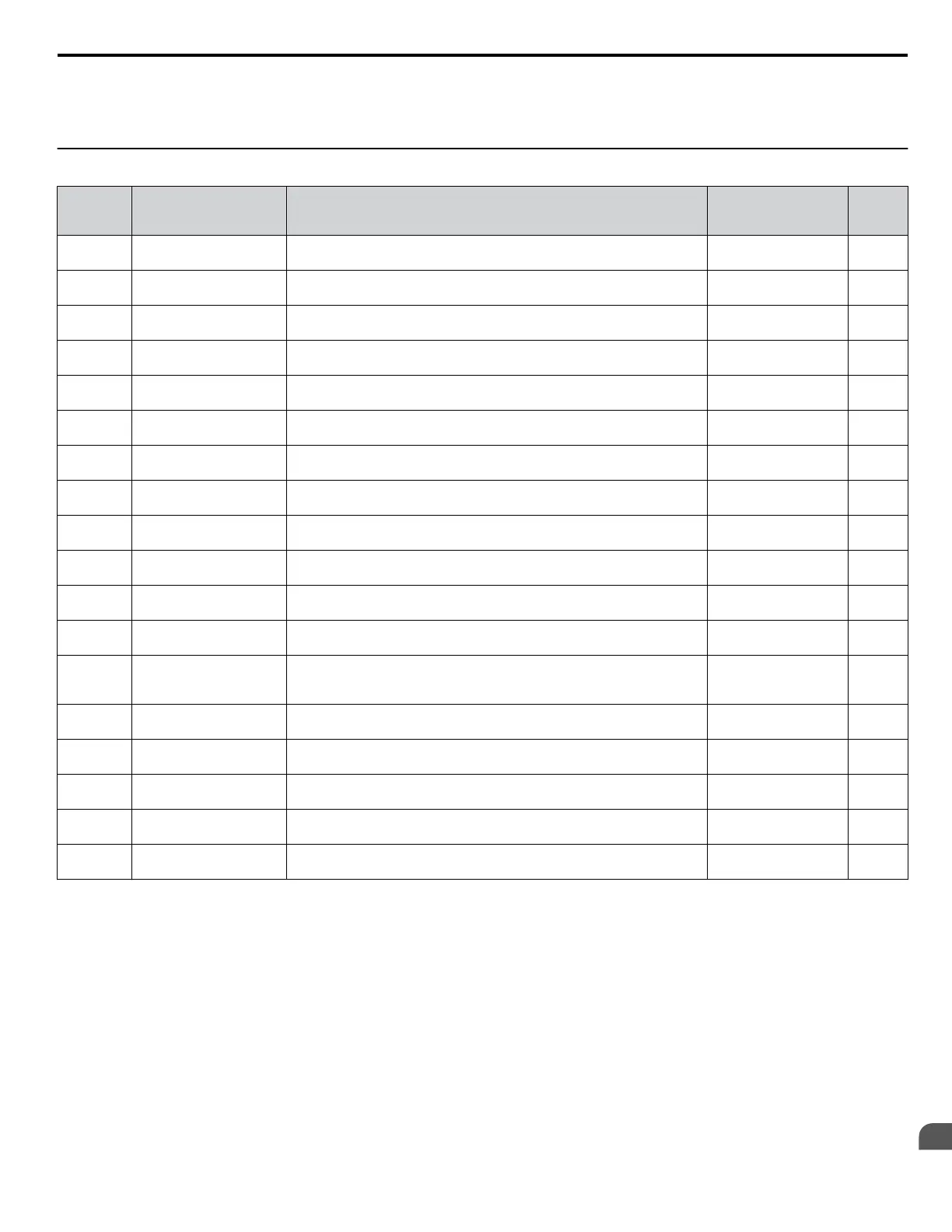
U2: Fault Trace
No.
(Addr.
Hex)
Name Description Analog Output Level Unit
U2-01
(80)
Current Fault
Displays the current fault. No signal output
available
–
U2-02
(81)
Previous Fault
Displays the previous fault. No signal output
available
–
U2-03
(82)
Frequency Reference at
Previous Fault
Displays the frequency reference at the previous fault. No signal output
available
0.01 Hz
U2-04
(83)
Output Frequency at
Previous Fault
Displays the output frequency at the previous fault. No signal output
available
0.01 Hz
U2-05
(84)
Output Current at Previous
Fault
Displays the output current at the previous fault. No signal output
available
<1>
<2>
U2-07
(86)
Output Voltage at
Previous Fault
Displays the output voltage at the previous fault. No signal output
available
0.1 Vac
U2-08
(87)
DC Bus Voltage at
Previous Fault
Displays the DC bus voltage at the previous fault. No signal output
available
1 Vdc
U2-09
(88)
Output Power at Previous
Fault
Displays the output power at the previous fault. No signal output
available
0.1 kW
U2-11
(8A)
Input Terminal Status at
Previous Fault
Displays the input terminal status at the previous fault. Displayed as in
U1-10.
No signal output
available
–
U2-12
(8B)
Output Terminal Status at
Previous Fault
Displays the output status at the previous fault. Displays the same status
displayed in U1-11.
No signal output
available
–
U2-13
(8C)
Drive Operation Status at
Previous Fault
Displays the operation status of the drive at the previous fault. Displays the
same status displayed in U1-12.
No signal output
available
–
U2-14
(8D)
Cumulative Operation
Time at Previous Fault
Displays the cumulative operation time at the previous fault. No signal output
available
1 h
U2-15
(7E0)
Soft Starter Speed
Reference at Previous
Fault
Displays the speed reference for the soft starter at the previous fault.
No signal output
available
0.01 Hz
U2-20
(8E)
Heatsink Temperature at
Previous Fault
Displays the temperature of the heatsink when the most recent fault
occurred.
No signal output
available
1 °C
U2-27
(7FA)
Motor Temperature at
Previous Fault (NTC)
Displays the temperature of the motor when the most recent fault occurred.
No signal output
available
1 °C
U2-30
(3008)
Date Year at Previous
Fault
Displays the year when the most recent fault occurred.
No signal output
available
–
U2-31
(3009)
Date Month and Day at
Previous Fault
Displays the date and day when the most recent fault occurred.
No signal output
available
–
U2-32
(300A)
Time Hours and Minutes at
Previous Fault
Displays the time when the most recent fault occurred.
No signal output
available
–
<1> The number of decimal places in the parameter value depends on the drive model and the ND selection. This value has two decimal places (0.01
A) if the drive is set for a maximum applicable motor capacity up to and including 11 kW, and one decimal place (0.1 A) if the maximum applicable
motor capacity is higher than 11 kW.
<2> When reading the value of this monitor via MEMOBUS/Modbus, a value of 8192 is equal to 100% of the drive rated output current.
B.12 U: Monitors
YASKAWA ELECTRIC TOEP YAIP1U 01B YASKAWA AC Drive - P1000 Quick Start Guide
229
B
Parameter List