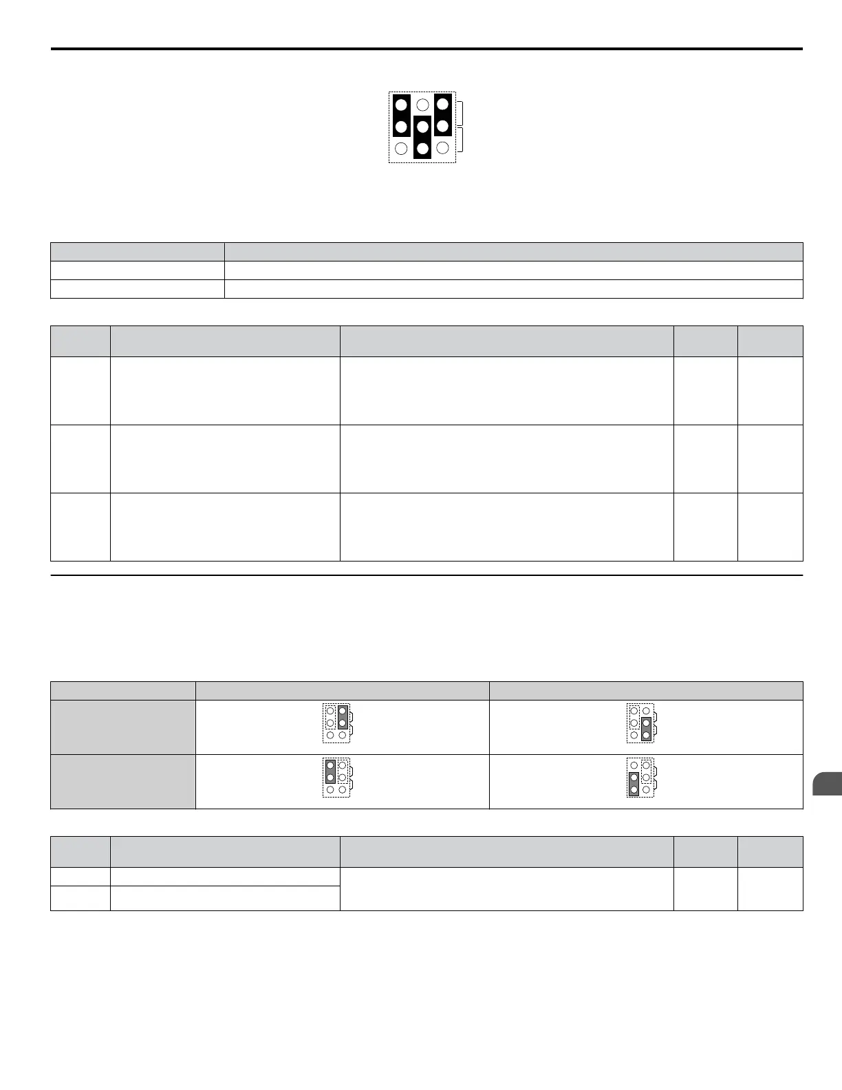
Figure 3.34 Terminal A2 Set to Current Input; A1 and A3 Set to Voltage Input
Table 3.13 Jumper S1 Settings
Setting Description
V (top position) Voltage input (-10 to +10 V or 0 to 10 V)
I (bottom position) Current input (4 to 20 mA or 0 to 20 mA)
Table 3.14 Voltage/Current Selection Parameter Details
No. Parameter Name Description
Setting
Range
Default
Setting
H3-01 Terminal A1 signal level selection
Selects the signal level for terminal A1.
0: 0 to 10 Vdc
1: 0 to 10 Vdc Bipolar
2: 4 to 20 mA
3: 0 to 20 mA
0 to 3 0
H3-05 Terminal A3 signal level selection
Selects the signal level for terminal A3.
0: 0 to 10 Vdc
1: 0 to 10 Vdc Bipolar
2: 4 to 20 mA
3: 0 to 20 mA
0 to 3 0
H3-09 Terminal A2 signal level selection
Selects the signal level for terminal A2.
0: 0 to 10 Vdc
1: 0 to 10 Vdc Bipolar
2: 4 to 20 mA
3: 0 to 20 mA
0 to 3 2
u
Terminal AM/FM Signal Selection
The signal type for terminals AM and FM can be set to either voltage or current output using jumper S5 on the terminal board
as explained in Table 3.15. When changing the setting of jumper S5, parameters H4-07 and H4-08 must be set accordingly.
The default selection is voltage output for both terminals.
Table 3.15 Jumper S5 Settings
Terminal Voltage Output Current Output
Terminal AM
AMFM
V
I
AMFM
V
I
Terminal FM
AMFM
V
I
AMFM
V
I
Table 3.16 Parameter H4-07 and H4-08 Details
No. Parameter Name Description
Setting
Range
Default
Setting
H4-07 Terminal AM signal level selection 0: 0 to 10 Vdc
1: -10 to 10 Vdc
2: 4 to 20 mA
0 to 2 0
H4-08 Terminal FM signal level selection
3.8 Control I/O Connections
YASKAWA ELECTRIC TOEP YAIP1U 01B YASKAWA AC Drive - P1000 Quick Start Guide
73
3
Electrical Installation