4.4 Powering Up the Drive
u
Powering Up the Drive and Operation Status Display
n
Powering Up the Drive
Review the following checklist before turning the power on.
Item to Check Description
Power supply voltage
200 V class: Three-phase 200 to 240 Vac 50/60 Hz
400 V class: Three-phase 380 to 480 Vac 50/60 Hz
600 V class: Three-phase 500 to 600 Vac 50/60 Hz
Properly wire the power supply input terminals (R/L1, S/L2, T/L3).
<1>
Check for proper grounding of drive and motor.
Drive output terminals and
motor terminals
Properly wire drive output terminals U/T1, V/T2, and W/T3 with motor terminals U, V, and W.
Control circuit terminals Check control circuit terminal connections.
Drive control terminal status Open all control circuit terminals (off).
Status of the load and connected
machinery
Decouple the motor from the load.
<1> Confirm the following when connecting models 4A0930 and 4A1200: Remove the jumpers on R1/L11, S1/L21, and T1/L31 when using 12-phase
rectification. Refer to 12-Phase Rectification on page 47 for details. When operating without 12-phase rectification, properly wire terminals R1/
L11, S1/L21, and T1/L31 in addition to terminals R/L1, S/L2, and T/L3.
n
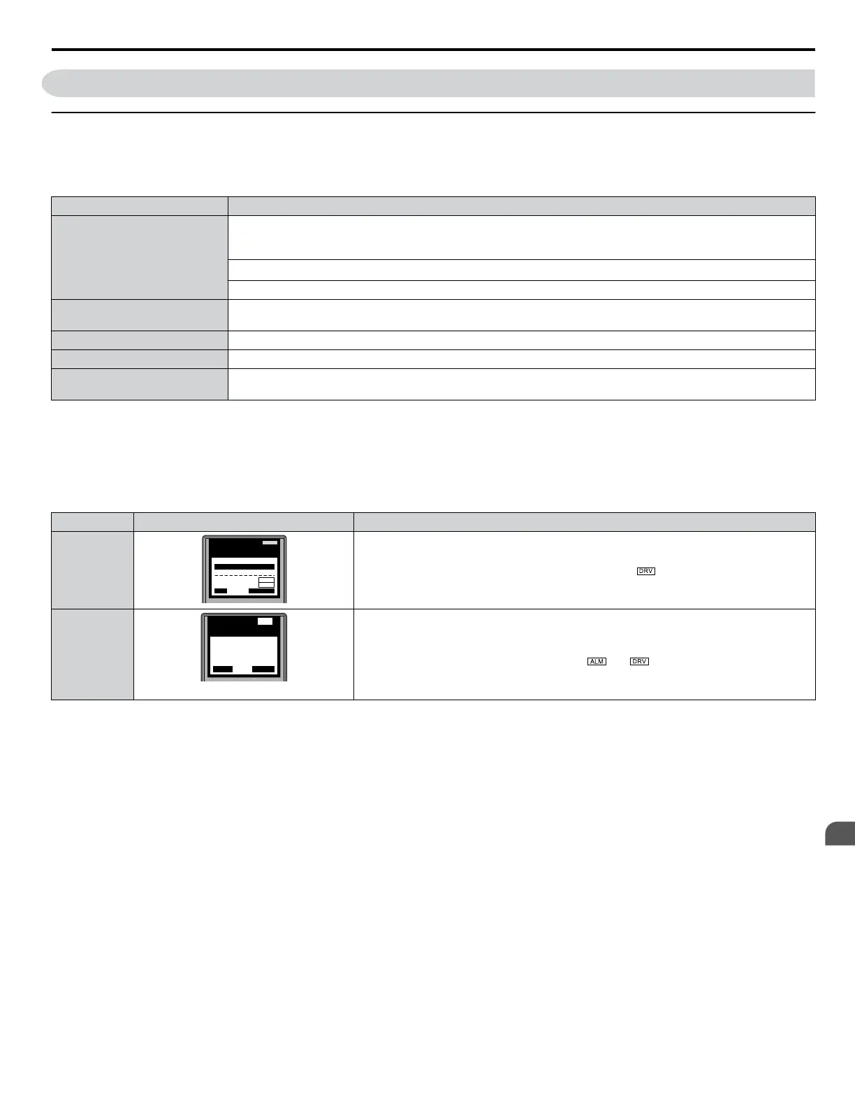
Status Display
When the power supply to the drive is turned on, the digital operator lights will appear as follows:
Status Name Description
Normal
Operation
LO
RE
ESC
RUN STOP
ENTERRESET
DIGITAL OPERATOR JVOP-180
ALARM
- MODE -
U1-01= 0.00Hz
U1-02= 0.00Hz
U1-03= 0.00 A
DRV
FREF (OPR)
Rdy
JOG FWD FWD/REV
LSEQ
LREF
The data display area displays the frequency reference. is lit.
Fault
LO
RE
ESC
RUN STOP
ENTERRESET
DIGITAL OPERATOR JVOP-180
ALM
- MODE -
EF3
Ext Fault S3
DRV
FWD
RESET
External fault (example)
Data displayed varies by the type of fault. Refer to Fault Displays, Causes, and Possible
Solutions on page 135 for more information. and are lit.
4.4 Powering Up the Drive
YASKAWA ELECTRIC TOEP YAIP1U 01B YASKAWA AC Drive - P1000 Quick Start Guide
89
4
Start-Up Programming &
Operation