u
Terminal Configuration
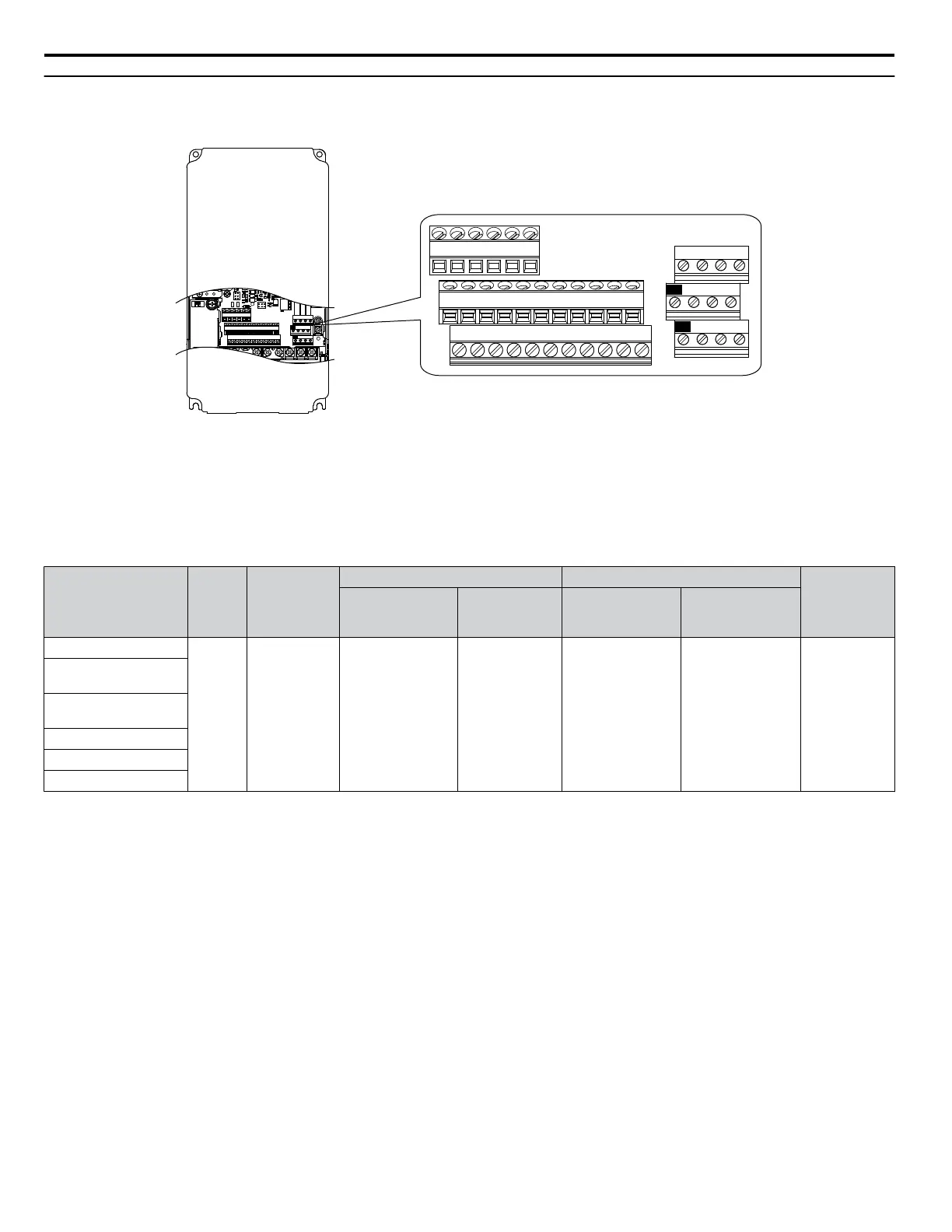
The control circuit terminals are arranged as shown in Figure 3.27.
E(G)
IG R+ R- S+ S-
S1 S2 S3 S4 S5 S6 S7 S8 SN SC SP
V+ AC A1 A2 A3 FM AM AC 24VRP AC
M1 M2 M3 M4
MD ME MF
MA MB MC
E(G)
IG R+ R- S+ S-
S1 S2 S3 S4 S5 S6 S7 S8 SN SC SP
V+ AC A1 A2 A3 FM AM AC 24VRP AC
M1 M2 M3 M4
MD ME MF
MA MB MC
Figure 3.27 Control Circuit Terminal Arrangement
n
Wire Size and Torque Specifications
Select appropriate wire type and gauges from Table 3.10. For simpler and more reliable wiring, use crimp ferrules on the wire
ends. Refer to Table 3.11 for ferrule terminal types and sizes.
Table 3.10 Wire Gauges
Terminal
Screw
Size
Tightening
Torque
N•m
(lb. in)
Bare Wire Terminal Ferrule-Type Terminal
Wire Type
Applicable
wire size
mm
2
(AWG)
Recomm.
wire size
mm
2
(AWG)
Applicable
wire size
mm
2
(AWG)
Recomm.
wire size
mm
2
(AWG)
S1-S8, SC, SN, SP
M3
0.5 to 0.6
(4.4 to 5.3)
Stranded wire:
0.2 to 1.0
(24 to 16)
Solid wire:
0.2 to 1.5
(24 to 16)
0.75 (18)
0.25 to 0.5
(24 to 20)
0.5 (20)
Shielded wire,
etc.
RP, V+, A1, A2, A3,
AC, 24 V
MA, MB, MC, MD, ME,
MF
M1-M4
FM, AM, AC
R+, R-, S+, S-, IG
3.7 Control Circuit Wiring
68
YASKAWA ELECTRIC TOEP YAIP1U 01B YASKAWA AC Drive - P1000 Quick Start Guide