n
Output Terminals
Table 3.8 lists the output terminals on the drive. Text in parenthesis indicates the default setting for each multi-function output.
Table 3.8 Control Circuit Output Terminals
Type No. Terminal Name (Function) Function (Signal Level) Default Setting Page
Fault Relay
Output
MA N.O.
30 Vdc, 10 mA to 1 A; 250 Vac, 10 mA to 1 A
Minimum load: 5 Vdc, 10 mA
108MB N.C. output
MC Fault output common
Multi-Function
Digital Output
<1>
MD N.O.
30 Vdc, 10 mA to 1 A; 250 Vac, 10 mA to 1 A
Minimum load: 5 Vdc, 10 mA
108
ME N.C. Output
MF Common (Speed agree)
M1
Multi-function digital output (During run)
30 Vdc, 10 mA to 1 A; 250 Vac, 10 mA to 1 A
Minimum load: 5 Vdc, 10 mA
M2
M3
Multi-function digital output (Zero speed)
M4
Monitor
Output
FM Analog monitor output 1 (Output frequency)
-10 to +10 Vdc, or 0 to +10 Vdc 208
AM Analog monitor output 2 (Output current)
AC Monitor common 0 V –
<1> Refrain from assigning functions to digital relay outputs that involve frequent switching, as doing so may shorten relay performance life. Switching
life is estimated at 200,000 times (assumes 1 A, resistive load).
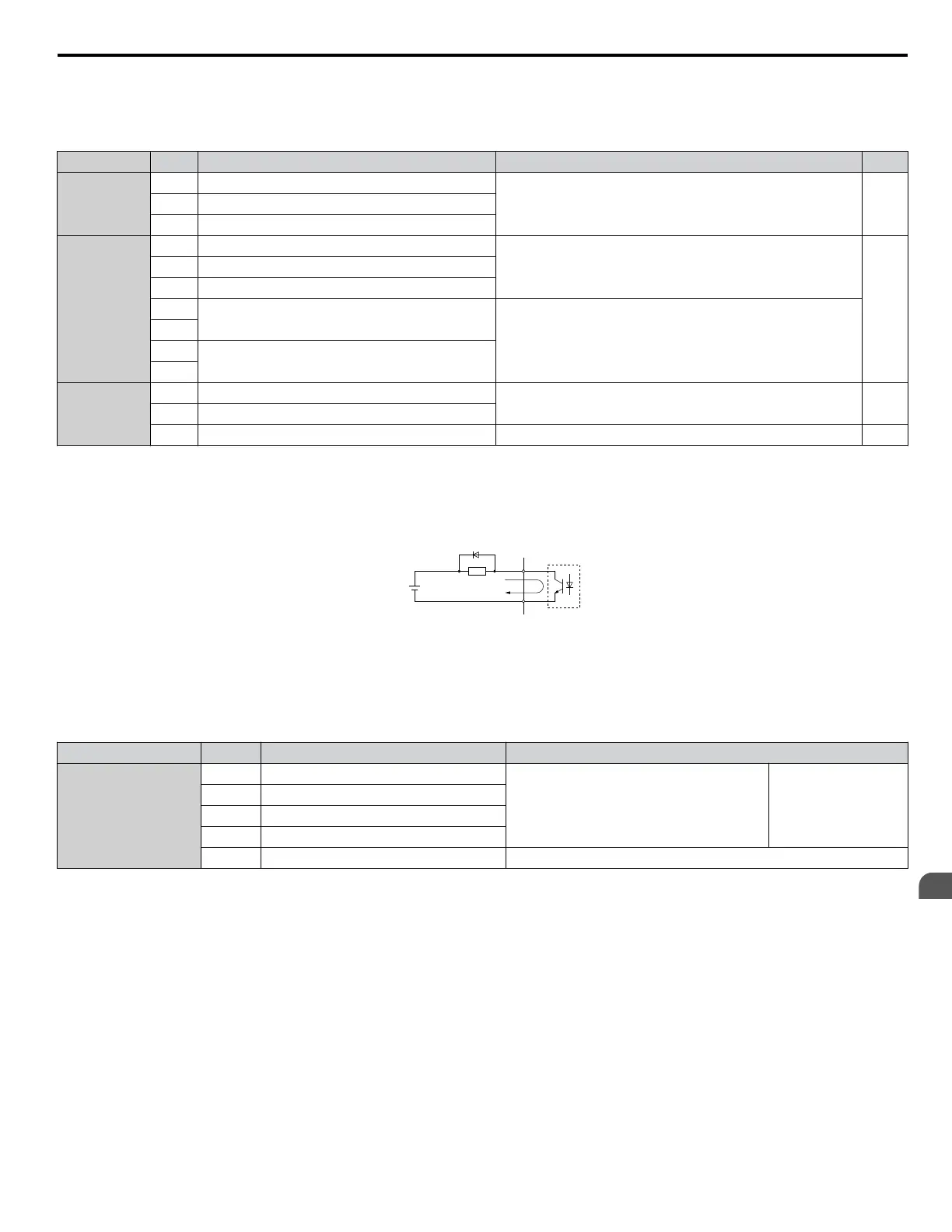
Connect a suppression diode as shown in Figure 3.26 when driving a reactive load such as a relay coil. Ensure the diode rating
is greater than the circuit voltage.
A
B
C
D
A – External power, 48 V max.
B – Suppression diode
C – Coil
D – 50 mA or less
Figure 3.26 Connecting a Suppression Diode
n
Serial Communication Terminals
Table 3.9 Control Circuit Terminals: Serial Communications
Type No. Signal Name Function (Signal Level)
MEMOBUS/Modbus
Communication
<1>
R+ Communications input (+)
MEMOBUS/Modbus communication: Use an
RS-422 or RS-485 cable to connect the drive.
RS-422/RS-485
MEMOBUS/Modbus
communication
protocol
115.2 kbps (max.)
R- Communications input (-)
S+ Communications output (+)
S- Communications output (-)
IG Shield ground 0 V
<1> Enable the termination resistor in the last drive in a MEMOBUS/Modbus network by setting DIP switch S2 to the ON position. Refer to the manual
section on Control I/O Connections for more information.
3.7 Control Circuit Wiring
YASKAWA ELECTRIC TOEP YAIP1U 01B YASKAWA AC Drive - P1000 Quick Start Guide
67
3
Electrical Installation
 Loading...


