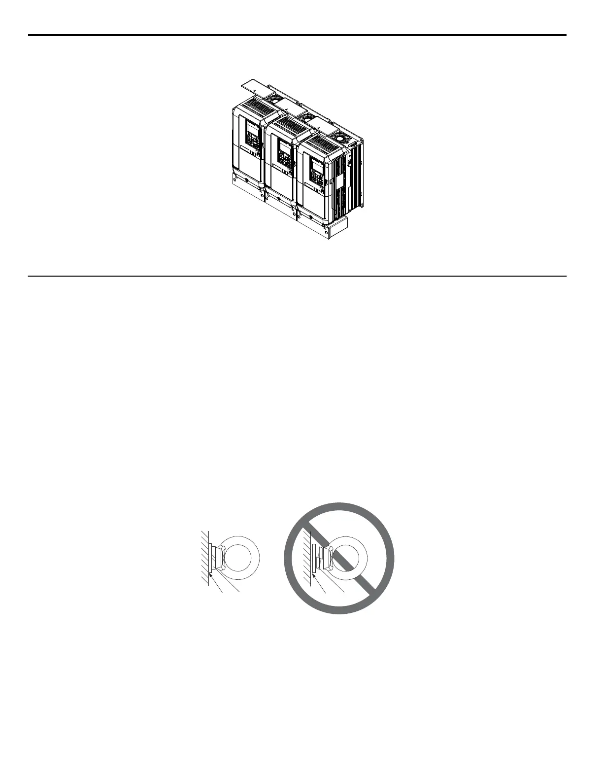
Remove the top protective covers of all drives as shown in Figure 2.4 when mounting IP20/NEMA Type 1 enclosure drives
side-by-side. Refer to Top Protective Cover on page 54 to remove and reattach the top protective cover.
Figure 2.4 IP20/NEMA 1 Side-by-Side Mounting in Enclosure
u
Instructions on Installation Using the Eye Bolts
Eye bolts are used to install the drive or to temporarily lift the drive when replacing it. Using the eye bolts, the drive can be
installed in an enclosure panel or on a wall. Do not leave the drive suspended by the wires in a horizontal or vertical position
for long periods of time. Do not transport the drive over long distances. Read the following precautions and instructions before
installing the drive.
WARNING!
Crush Hazard. Observe the following instructions and precautions. Failure to comply could result in serious injury or death from
falling equipment.
Only use vertical suspension to temporarily lift the drive during installation to an enclosure panel. Do not use vertical suspension to transport
the drive.
Use screws to securely affix the drive front cover, terminal blocks, and other drive components prior to vertical suspension.
Do not subject the drive to vibration or impact greater than 1.96 m/s
2
(0.2 G) while it is suspended by the wires.
Do not leave the drive unattended while it is suspended by the wires.
Do not attempt to flip the drive over while it is suspended by the wires.
n
Horizontal Suspension of Drive Models 2A0360, 2A0415, and 4A0250 to 4A0675
To make a wire hanger or frame for use when lifting the drive with a crane, lay the drive in a horizontal position and pass a
wire through the holes of the four eye bolts.
NOTICE:
Damage to Equipment. When lifting the drive, confirm that the spring washer is fully closed. Failure to comply may deform or
damage the drive when lifted.
A – No space between drive and washer
B – Spring washer fully closed
C – Space between drive and washer
D – Spring washer open
Figure 2.5 Spring Washer
2.1 Mechanical Installation
28
YASKAWA ELECTRIC TOEP YAIP1U 01B YASKAWA AC Drive - P1000 Quick Start Guide