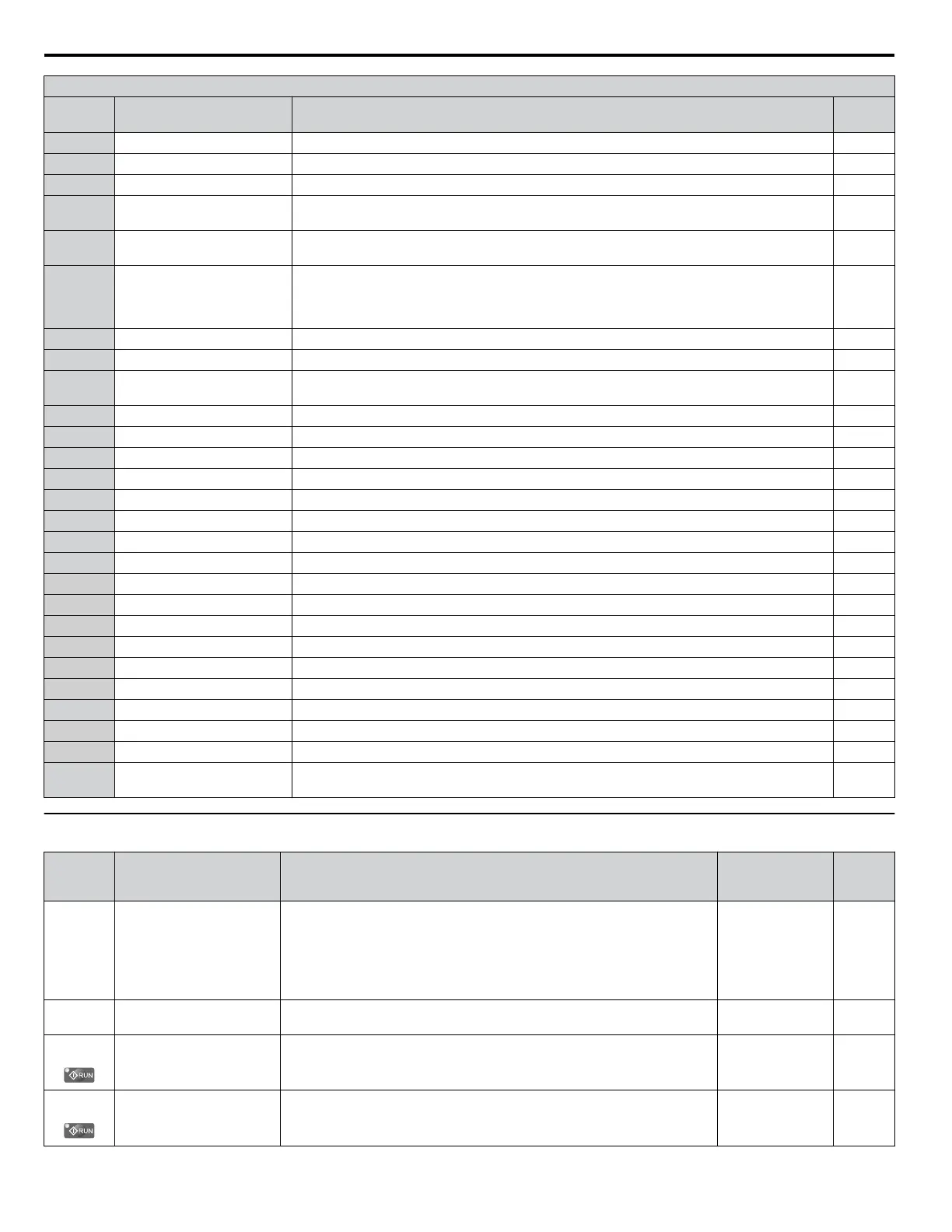
H2 Multi-Function Digital Output Settings
H2-oo
Setting
Function Description Page
1E Restart enabled Closed: An automatic restart is performed –
1F Motor overload alarm (oL1) Closed: oL1 is at 90% of its trip point or greater. An oH3 situation also triggers this alarm. –
20 Drive overheat pre-alarm (oH) Closed: Heatsink temperature exceeds the parameter L8-02 value. –
22
Mechanical weakening
detection
Closed: Mechanical weakening detected.
–
2F Maintenance period
Closed: Cooling fan, electrolytic capacitors, IGBTs, or the soft charge bypass relay may require
maintenance.
–
37 During frequency output
Open: Either the drive has stopped or baseblock, DC Injection Braking, or Initial Excitation is
being performed.
Closed: Drive is running the motor (not in a baseblock state and DC Injection is not being
performed).
–
38 Drive enabled
Closed: Multi-function input set for “Drive enable” is closed (H1-oo = 6A)
–
39 Watt hour pulse output Output units are determined by H2-06. Outputs a pulse every 200 ms to indicate the kWh count. –
3C LOCAL/REMOTE status
Open: REMOTE
Closed: LOCAL
–
3D During speed search Closed: Speed Search is being executed. –
3E PID feedback low Closed: PID feedback level is too low. –
3F PID feedback high Closed: The PID feedback level is too high. –
4A During KEB Ride-Thru Closed: KEB Ride-Thru is being performed. –
4C During fast stop Closed: A Fast Stop command has been entered from the operator or input terminals. –
4D oH Pre-alarm time limit Closed: oH pre-alarm time limit has passed. –
4E Braking transistor fault (rr) Closed: The built-in dynamic braking transistor failed. –
4F Braking resistor overheat (oH) Closed: The dynamic braking resistor has overheated. –
50 Waiting to Run Closed: b1-11 Timer is active. –
51 Sequence timer 1 Closed: Sequence timer 1 is active. –
52 Sequence timer 2 Closed: Sequence timer 2 is active. –
53 Sequence timer 3 Closed: Sequence timer 3 is active. –
54 Sequence timer 4 Closed: Sequence timer 4 is active. –
58 Underload detection Closed: Underload is detected. –
60 Internal cooling fan alarm Closed: Internal cooling fan alarm –
71 Secondary PI Feedback Low Closed: PI2 feedback level is too low. –
72 Secondary PI Feedback High Closed: The PI2 feedback level is too high. –
100 to 192
Function 0 to 92 with inverse
output
Inverts the output switching of the multi-function output functions.
Set the last two digits of 1oo to reverse the output signal of that specific function.
–
u
H3: Multi-Function Analog Inputs
No.
(Addr.
Hex)
Name Description Values Page
H3-01
(410)
Terminal A1 Signal Level
Selection
0: 0 to 10 V
1: -10 to 10 V
2: 4 to 20 mA
3: 0 to 20 mA
Note: Use Jumper S1 to set input terminal A1 for a current or voltage
input signal.
Default: 0
Range: 0 to 3
110
H3-02
(434)
Terminal A1 Function
Selection
Sets the function of terminal A1. Default: 0
Range: 0 to 26
110
H3-03
(411)
Terminal A1 Gain Setting
Sets the level of the input value selected in H3-02 when 10 V is input at
terminal A1.
Default: 100.0%
Min.: -999.9
Max.: 999.9
110
H3-04
(412)
Terminal A1 Bias Setting
Sets the level of the input value selected in H3-02 when 0 V is input at terminal
A1.
Default: 0.0%
Min.: -999.9
Max.: 999.9
110
B.6 H Parameters: Multi-Function Terminals
206
YASKAWA ELECTRIC TOEP YAIP1U 01B YASKAWA AC Drive - P1000 Quick Start Guide

 Loading...


