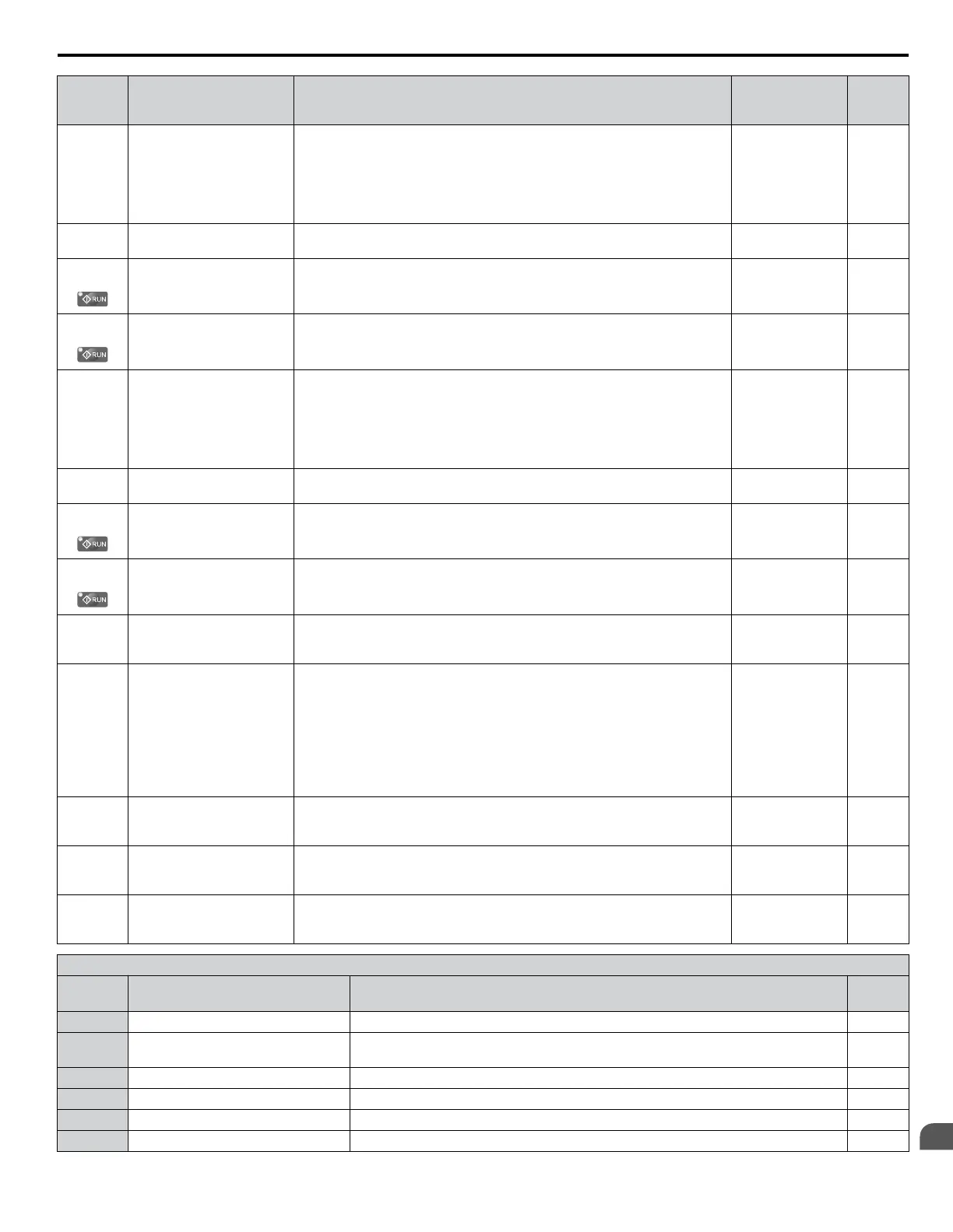
No.
(Addr.
Hex)
Name Description Values Page
H3-05
(413)
Terminal A3 Signal Level
Selection
0: 0 to 10 V
1: -10 to 10 V
2: 4 to 20 mA
3: 0 to 20 mA
Note: Use Jumper S1 to set input terminal A3 for a current or voltage
input signal.
Default: 0
Range: 0 to 3
111
H3-06
(414)
Terminal A3 Function
Selection
Sets the function of terminal A3. Default: 2
Range: 0 to 26
111
H3-07
(415)
Terminal A3 Gain Setting
Sets the level of the input value selected in H3-06 when 10 V is input at
terminal A3.
Default: 100.0%
Min.: -999.9
Max.: 999.9
111
H3-08
(416)
Terminal A3 Bias Setting
Sets the level of the input value selected in H3-06 when 0 V is input at terminal
A3.
Default: 0.0%
Min.: -999.9
Max.: 999.9
111
H3-09
(417)
Terminal A2 Signal Level
Selection
0: 0 to 10 V
1: -10 to 10 V
2: 4 to 20 mA
3: 0 to 20 mA
Note: Use Jumper S1 to set input terminal A2 for a current or voltage
input signal.
Default: 2
Range: 0 to 3
112
H3-10
(418)
Terminal A2 Function
Selection
Sets the function of terminal A2. Default: 0
Range: 0 to 26
112
H3-11
(419)
Terminal A2 Gain Setting
Sets the level of the input value selected in H3-10 when 10 V (20 mA) is input
at terminal A2.
Default: 100.0%
Min.: -999.9
Max.: 999.9
112
H3-12
(41A)
Terminal A2 Bias Setting
Sets the level of the input value selected in H3-10 when 0 V (0 or 4 mA) is
input at terminal A2.
Default: 0.0%
Min.: -999.9
Max.: 999.9
112
H3-13
(41B)
Analog Input Filter Time
Constant
Sets a primary delay filter time constant for terminals A1, A2, and A3. Used
for noise filtering.
Default: 0.03 s
Min.: 0.00
Max.: 2.00
–
H3-14
(41C)
Analog Input Terminal
Enable Selection
Determines which analog input terminals will be enabled when a digital input
programmed for “Analog input enable” (H1-oo = C) is activated.
1: Terminal A1 only
2: Terminal A2 only
3: Terminals A1 and A2 only
4: Terminal A3 only
5: Terminals A1 and A3
6: Terminals A2 and A3
7: All terminals enabled
Default: 7
Range: 1 to 7
–
H3-16
(2F0)
Terminal A1 Offset
Adds an offset when the analog signal to terminal A1 is at 0 V. Default: 0
Min.: -500
Max.: 500
–
H3-17
(2F1)
Terminal A2 Offset
Adds an offset when the analog signal to terminal A2 is at 0 V. Default: 0
Min.: -500
Max.: 500
–
H3-18
(2F2)
Terminal A3 Offset
Adds an offset when the analog signal to terminal A3 is at 0 V. Default: 0
Min.: -500
Max.: 500
–
H3 Multi-Function Analog Input Settings
H3-oo
Setting
Function Description Page
0 Frequency bias 10 V = E1-04 (maximum output frequency) –
1 Frequency gain
0 to 10 V signal allows a setting of 0 to 100%. -10 to 0 V signal allows a setting of -100
to 0%.
–
2 Auxiliary frequency reference 1 10 V = E1-04 (maximum output frequency) –
3 Auxiliary frequency reference 2 10 V = E1-04 (maximum output frequency) –
4 Output voltage bias 10 V = E1-05 (motor rated voltage) –
5 Accel/decel time gain 10 V = 100% –
B.6 H Parameters: Multi-Function Terminals
YASKAWA ELECTRIC TOEP YAIP1U 01B YASKAWA AC Drive - P1000 Quick Start Guide
207
B
Parameter List

 Loading...


