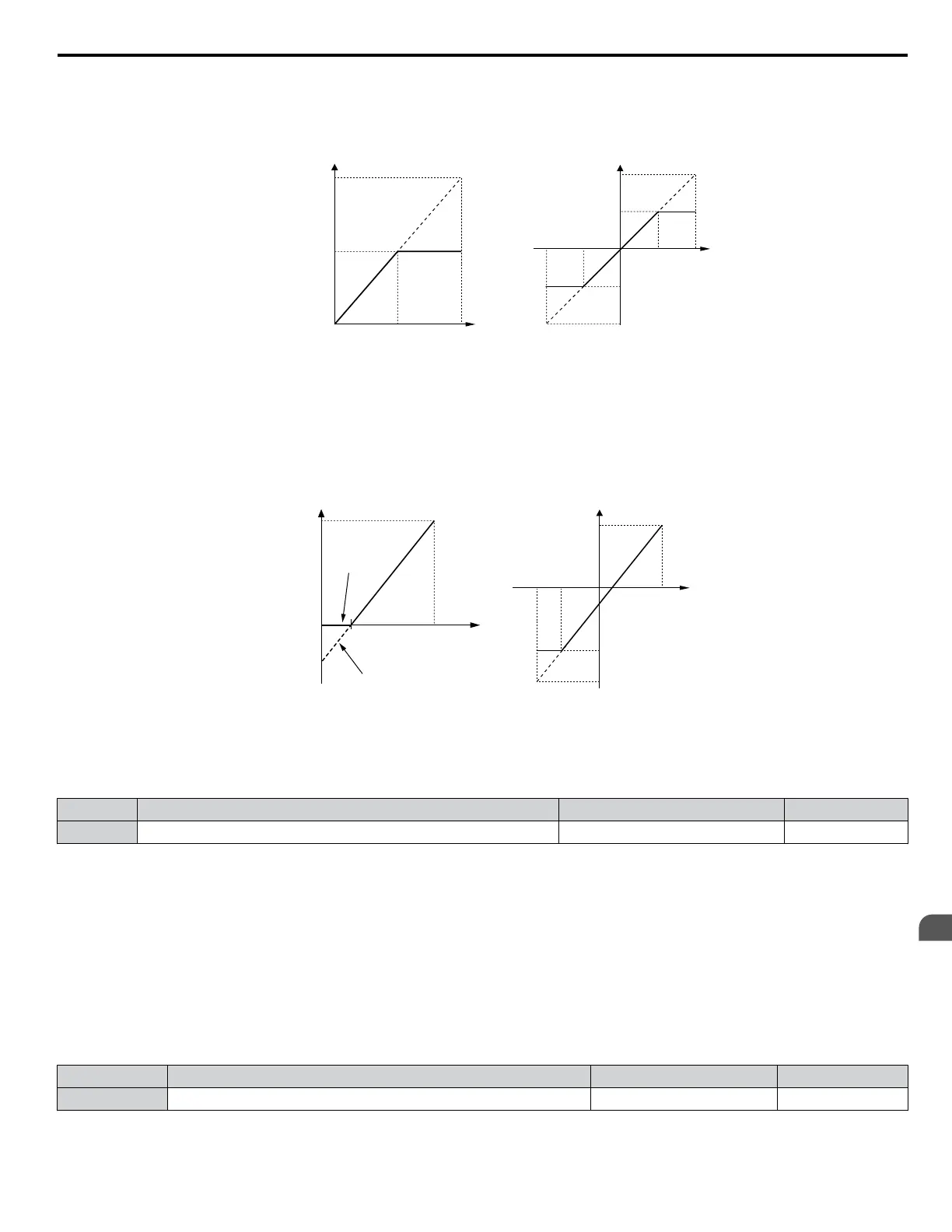
A 10 Vdc input is equivalent to a 200% frequency reference and 5 Vdc is equivalent to a 100% frequency reference. Since
the drive output is limited by the maximum frequency parameter (E1-04), the frequency reference will be equal to E1-04
above 5 Vdc.
100%
-100%
5 V
10 V
-5 V-10 V
E1-04
E1-04
H3-01 = 0 H3-01 = 1
0 V
10 V5 V
0 V
Gain = 200 % Gain = 200 %
100 %
Frequency
reference
Bias = 0 %
E1-04
Gain = -200 %
Figure 4.23 Frequency Reference Setting by Analog Input with Increased Gain
• Gain H3-03 = 100%, bias H3-04 = -25%, terminal A1 as frequency reference input:
An input of 0 Vdc will be equivalent to a -25% frequency reference.
When parameter H3-01 = 0, the frequency reference is 0% between 0 and 2 Vdc input.
When parameter H3-01 = 1, the motor will rotate in reverse between -10 and 2 Vdc input.
2.0 V
10 V
-6.0 V-10 V
E1-04
0
-100%
-150%
2.0 V 10 V
100 %
Frequency
reference
-25%
-25%
H3-01 = 0
H3-01 = 1
H3-01 = 0 H3-01 = 1
100%
Analog Input
Voltage
Analog Input
Voltage
Figure 4.24 Frequency Reference Setting by Analog Input with Negative Bias
n
H3-05: Terminal A3 Signal Level Selection
Determines the function assigned to analog input terminal A3.
No. Name Setting Range Default
H3-05 Terminal A3 Signal Level Selection 0 to 3 0
Setting 0: 0 to 10 Vdc
The input level is 0 to 10 Vdc. See the explanation provided for H3-01. Refer to Setting 0: 0 to 10 Vdc on page 110.
Setting 1: 0 to 10 Vdc Bipolar
The input level is -10 to 10 Vdc. See the explanation provided for H3-01. Refer to Setting 1: 0 to 10 Vdc Bipolar on page
110.
Setting 2: 4 to 20 mA
Setting 3: 0 to 20 mA
n
H3-06: Terminal A3 Function Selection
Determines the function assigned to analog input terminal A3.
No. Name Setting Range Default
H3-06 Terminal A3 Function Selection 0 to 26 2
n
H3-07, H3-08: Terminal A3 Gain and Bias Setting
Parameter H3-07 sets the level of the selected input value that is equal to 10 Vdc input at terminal A3 (gain).
4.6 Basic Drive Setup Adjustments
YASKAWA ELECTRIC TOEP YAIP1U 01B YASKAWA AC Drive - P1000 Quick Start Guide
111
4
Start-Up Programming &
Operation

 Loading...


