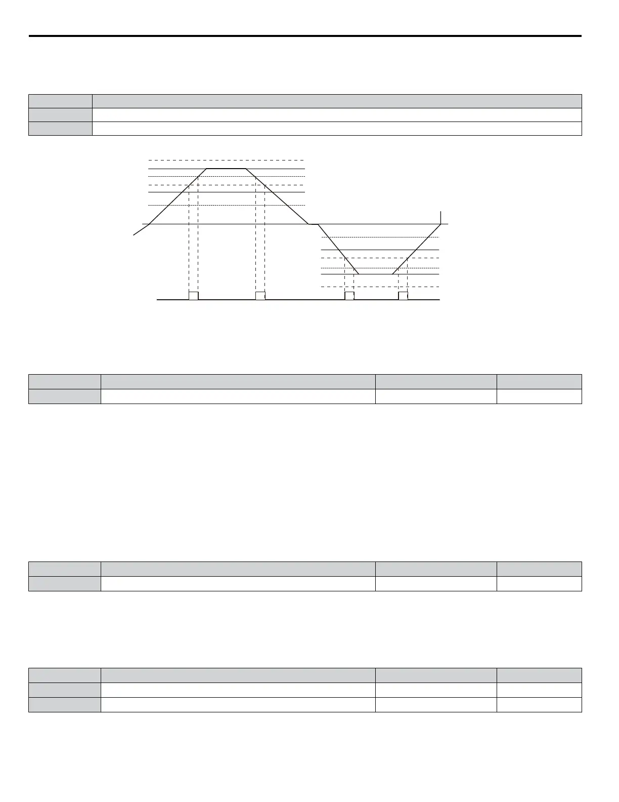
Setting 3: User-Set Speed Agree 1 (f
ref
/f
set
Agree 1)
Closes when the actual output frequency and the frequency reference are within the speed agree width (L4-02) of the
programmed speed agree level (L4-01).
Status Description
Open Output frequency or motor speed and frequency reference are not both within the range of L4-01 ±L4-02.
Closed Output frequency or motor speed and the frequency reference are both within the range of L4-01 ±L4-02.
Note: Frequency detection works in forward and reverse. The value of L4-01 is used as the detection level for both directions.
Frequency reference
Frequency reference + L4-02
Frequency reference – L4-02
L4-01
L4-01 + L4-02
L4-01 – L4-02
Frequency reference
Frequency reference + L4-02
Frequency reference – L4-02
–L4-01
–L4-01 + L4-02
–L4-01 – L4-02
During
Forward
During Reverse
Output frequency
0 Hz
OFF OFF OFF
ON ON
ON
ON
Output frequency
User Set
Speed Agree 1
Figure 4.22 User Set Speed Agree 1 Time Chart
n
H3-01: Terminal A1 Signal Level Selection
Selects the input signal level for analog input A1.
No. Name Setting Range Default
H3-01 Terminal A1 Signal Level Selection 0 to 3 0
Setting 0: 0 to 10 Vdc
The input level is 0 to 10 Vdc. The minimum input level is limited to 0%, so that a negative input signal due to gain and bias
settings will be read as 0%.
Setting 1: 0 to 10 Vdc Bipolar
The input level is -10 to 10 Vdc. If the resulting voltage is negative after being adjusted by gain and bias settings, then the
motor will rotate in reverse.
Setting 2: 4 to 20 mA
Setting 3: 0 to 20 mA
n
H3-02: Terminal A1 Function Selection
Selects the input signal level for analog input A1.
No. Name Setting Range Default
H3-02 Terminal A1 Function Selection 0 to 26 0
n
H3-03, H3-04: Terminal A1 Gain and Bias Settings
Parameter H3-03 sets the level of the selected input value that is equal to 10 Vdc input at terminal A1 (gain).
Parameter H3-04 sets the level of the selected input value that is equal to 0 V input at terminal A1 (bias).
Use both parameters to adjust the characteristics of the analog input signal to terminal A1.
No. Name Setting Range Default
H3-03 Terminal A1 Gain Setting -999.9 to 999.9% 100.0%
H3-04 Terminal A1 Bias Setting -999.9 to 999.9% 0.0%
Setting Examples
• Gain H3-03 = 200%, bias H3-04 = 0, terminal A1 as frequency reference input (H3-02 = 0):
4.6 Basic Drive Setup Adjustments
110
YASKAWA ELECTRIC TOEP YAIP1U 01B YASKAWA AC Drive - P1000 Quick Start Guide
 Loading...


