Deceleration time is too short and excessive
regenerative energy is flowing back into the
drive
• Check the load, deceleration time, and speed.
• Reduce the load inertia.
• Increase the deceleration times (C1-01 to C1-04).
• Replace the dynamic braking option with a larger device that can handle the power that is discharged.
The duty cycle is too high Check the duty cycle. Maximum of 3% duty cycle is available when L8-01 = 1.
Excessive braking inertia
Recalculate braking load and braking power. Reduce the braking load by adjusting braking resistor
settings.
The braking operation duty cycle is too high
Check the braking operation duty cycle. Braking resistor protection for ERF-type braking resistors
(L8-01 = 1) allows a braking duty cycle of maximum 3%.
The proper braking resistor has not been
installed
• Check the specifications and conditions for the braking resistor device.
• Select the optimal braking resistor.
Note: The magnitude of the braking load trips the braking resistor overheat alarm, NOT the surface temperature. Using the braking resistor more
frequently than its rating permits will trip the alarm even when the braking resistor surface is not very hot.
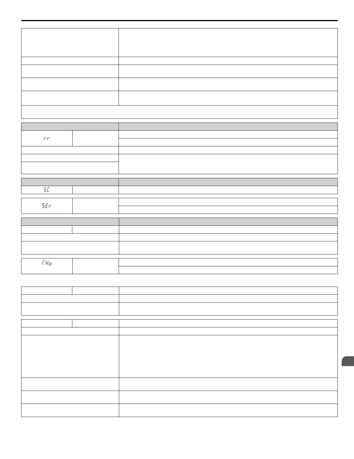
Digital Operator Display Fault Name
rr
Dynamic Braking Transistor
The built-in dynamic braking transistor failed.
Cause Possible Solution
The braking transistor is damaged • Cycle power to the drive and check for reoccurrence of the fault.
• Replace either the control board or the entire drive. For instructions on replacing the control board,
contact Yaskawa or a Yaskawa representative.
The control circuit is damaged
Digital Operator Display Fault Name
SC IGBT Short Circuit or Ground Fault
SEr
Too Many Speed Search Restarts
The number of Speed Search restarts exceeded the value set to b3-19.
Digital Operator Display Fault Name
TdE TdE Time Data Error
Cause Possible Solution
An error has occurred in the Real-Clock Time
function of the digital operator
Replace the digital operator. For instructions on replacing the digital operator, contact Yaskawa or your
nearest sales representative.
<1>
THo
Thermistor Disconnect
The thermistor that detects motor temperature has become disconnected.
<1> Detected in models 4A0930 and 4A1200.
TIE TIE Time Interval Error
Cause Possible Solution
An error has occurred in the Real-Clock Time
function of the digital operator
Replace the digital operator. For instructions on replacing the digital operator, contact Yaskawa or your
nearest sales representative.
TIM TIM Time Not Set
Cause Possible Solution
The Real-Time Clock for the digital operator
is not set in parameter o4-17
• The drive is a new drive, first power-up
condition
• o4-17 was set to 2, Reset, by the user,
manually clearing the Real-Time Clock
data.
Set o4-17 to 1 to set the time for the digital operator.
The drive will display the "TIM" alarm (Time Not Set) when the Real time Clock is not set . Additionally,
at power up, if the "TIM" condition is present, the drive will automatically switch to the time setting
screen (o4-17 = 1) for 30 seconds to prompt the user to set the Real-Time Clock.
The user did not set the Real Time Clock when
prompted following power-up.
Cycle power to the drive and set the Real Time Clock within 30 seconds of power-up, or set the clock
manually via parameter o4-17.
The digital operator battery is low or the
battery has been replaced
Replace the digital operator battery and set the Real-Time Clock.
An error has occurred in the Real-Time Clock
function of the digital operator
Replace the digital operator. For instructions on replacing the digital operator, contact Yaskawa or your
nearest sales representative.
5.2 Fault Detection
YASKAWA ELECTRIC TOEP YAIP1U 01B YASKAWA AC Drive - P1000 Quick Start Guide
143
5
Troubleshooting
 Loading...


