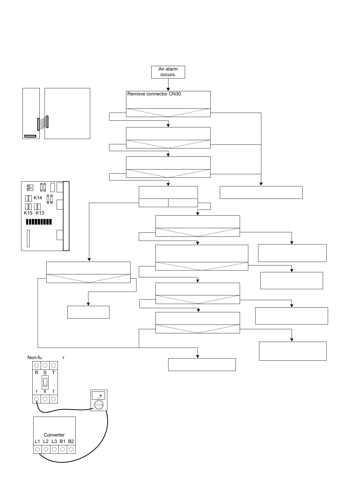
AL-4304 (CONVERTER INPUT POWER ERROR)
CN30
CN1
CN7
K14
K15 K13
Converter
L1 L2 L3 B1 B2
rst
RST
Non-fuse breaker
An alarm
occurs.
Remove connector CN30 of the
WRCA circuit board and re-insert it.
(See Fig. 27.)
Alarm?
Yes No
Check connector CN1 of the
converter. (See Fig. 27.)
Alarm?
Yes No
Check connector CN7 of the
converter. (See Fig. 27.)
Alarm?
Yes No
Is the contactor ON?
NoYes
Confirm that the contactor is not
stuck. (See Fig. 29.)
Alarm?
Yes No
Confirm that relay K15 of the XTU01
circuit board is not stuck or disconnected.
(See Fig. 28.)
Replace the XTU01 circuit board.
Alarm?
Yes No
Replace the WRCA01 circuit board.
Alarm?
Yes No
Contact your Yaskawa
representative.
Replace the converter.
Alarm?
Yes No
Continue normal
operation.
Alarm?
Yes
No
Converter SERVOPACK
Tester
(Measure the
resistance.)
XIU01-
!!
XTU01
Fig. 27
Fig. 28
Fig. 29
After turning OFF the non-fuse breaker, measure the
resistance between the non-fuse breaker's secondary
terminals and the converter's input power supply
terminals to confirm that all are open.
Measure the resistance between r and L1, s and L2,
and t and L3.
Continue normal operation.
The defective WRCA01 circuit
board caused the alarm.
Continue normal operation.
The defective XTU01 circuit
board caused the alarm.
Continue normal operation.
The poor contact caused the alarm.
Continue normal operation.
The defective relay caused
the alarm.
Continue normal operation.
The stuck contactor caused
the alarm.
 Loading...