Service Kit Installation Procedures
4–70 www.zoll.com 906-0731-04-01 Rev. C
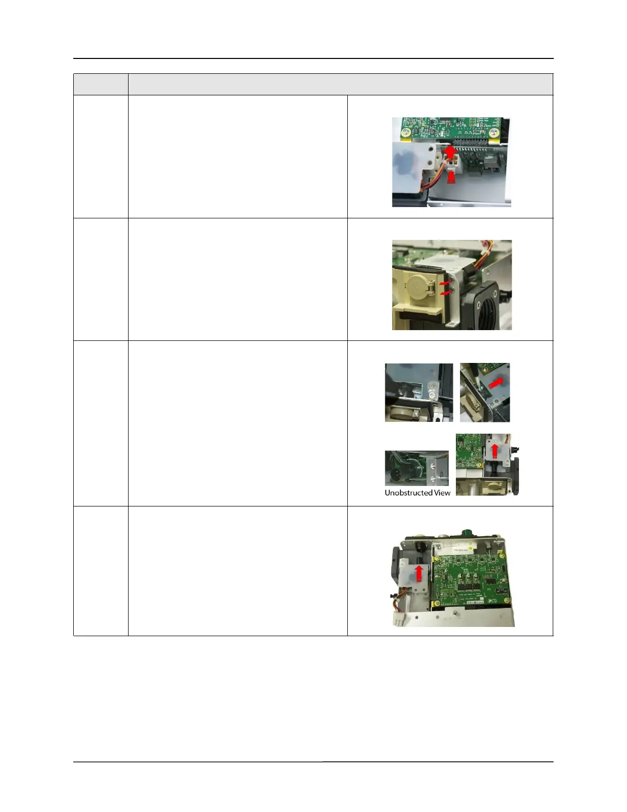
8 Disconnect the Power Input cable from the PIM
board by pressing on the locking latch and pulling
the cable straight up from the connector.
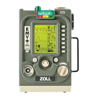
9 Loosen and remove the two 4-40 x 1/4 screws
holding the Power Input to the connector panel.
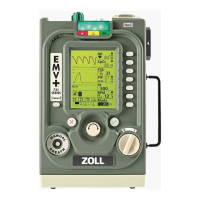
10 Using two small flat blade screwdrivers, separate
the two locking tabs on the power plug and pull
the power input assembly away from the
connector panel.
11 Insert the new power input assembly into the
connector panel socket and pull on the assembly
to ensure the locking tabs have engaged.
Step Action