Service Kit Installation Procedures
4–44 www.zoll.com 906-0731-04-01 Rev. C
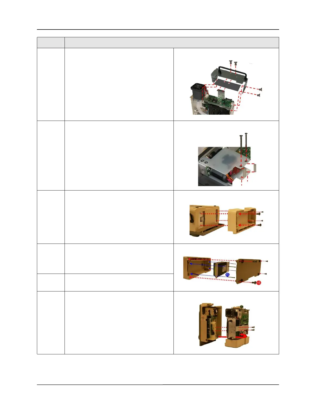
12 Secure the replacement Chassis to the ventilator
module using the two 6-32 x 1/4 screws (provided
in the kit) with the SpO
2
insulator, the two 8-32 x
1/4, and the two
6-32 x 5/16 screws.
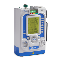
13 Secure the Power Input assembly to the Chassis
using the two spacers and two
4-40 x 1 1/4 screws.
Note: Do not over-tighten the screws.
(Maximum torque - 3.5 in.- lb.)
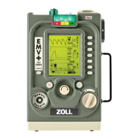
14 Rotate battery compartment to mate with upper
and lower case cutouts and press firmly into place.
Secure with four 632 x 5/16 screws provided.
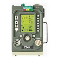
15 Re-assemble the battery by connecting its cable to
the connector (pull lightly on cable to ensure it is
locked in place) then tightening the four 6-32 x 2
1/4 screws.
16 Re-assemble the battery compartment cover by
tightening the four 6-32 x 5/16 screws.
17 Place the front case assembly over the ventilator
module and tighten the two 4-40 x 1/4 screws to
the dovetail mounting bracket.
Reconnect the ribbon cable unto the PIM board.
Make sure the two ejector latches are secured.
Step Action