Warning
Never remove the main board or camera electronics from under the lower
cover while installing 2N
®
Helios IP. Do not disconnect the camera flat
cable from the main board. Do not bend and press upon the flat cable
either.
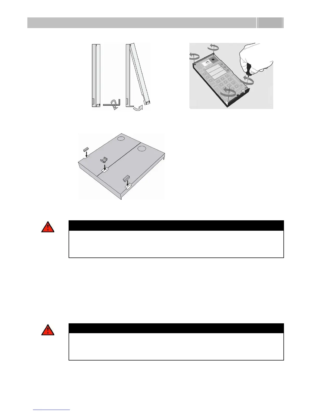
4. In multiple-module assemblies connect the boxes according to
Figure 2.4, placing the basic module to the left and the extending modules to
the right. The interconnecting cable shall be connected later!
5. Install blank modules on the unused side holes as shown in Figure 2.4.
6. If you are installing a roof module, put it on the wall now.
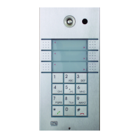
7. Fix 2N
®
Helios IP on the wall with screws as shown in Figure 2.6. Carry the
supply cables (Ethernet, lock, power cables) to the basic module box through
one of the holes.
Warning
Make sure that the mounting surface for the 2N
®
Helios IP door
communicator is perfectly flat. Avoid mechanical overload upon the
bottom part of the cover. An incorrect installation on an uneven surface
may lead to cover deformation and thus product malfunctions.