24
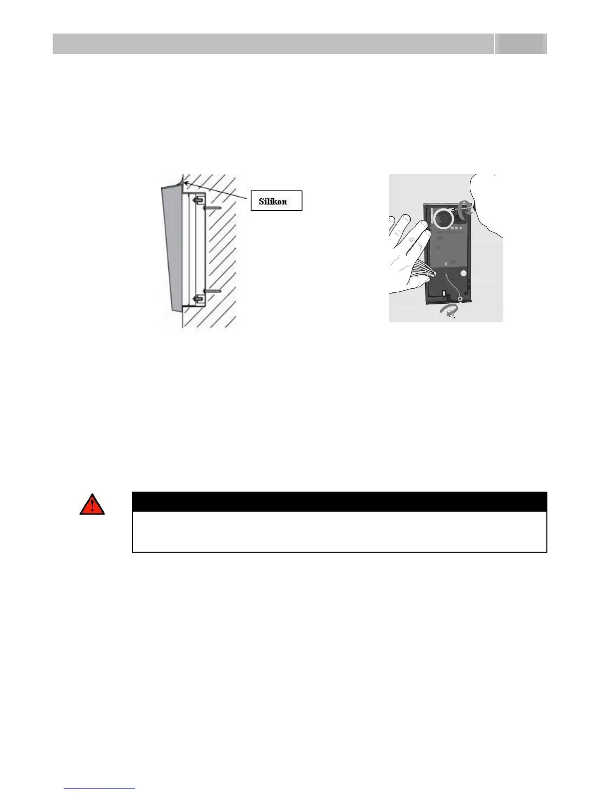
8. While installing a roof module, paste its top and side edges to the wall using
silicon glue as shown in Figure 2.5 to prevent water from flowing into the box
along or around the cables.
9. Connect the cables as described in subsection 2.4, Mounting – Electrical
Installation. Make sure that the cables are not squeezed while installing the
plastic cover. For the correct cable installation, refer to Figure 2.7.
10. Remove the protective foil from the display (for display-equipped 2N
®
Helios
IP versions only).
11. Make sure that the cables are placed properly inside and that none of them
obstructs a perfect cover closure.
12. Make sure that the three loudspeaker holder feet fit into the board holes.
Keep the required loudspeaker position to make the seal work properly.
13. Having mounted the unit on the wall and connected all cables, replace the
plastic cover using cross-recessed screws.
Warning
Remember to tighten all the four corner screws to fix the loudspeaker seal
after electric installation to avoid water in-leak! A PH2 cross-head
screwdriver is recommended.
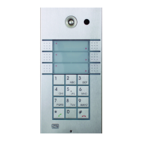
14. Take out the name plates from the plastic cover as shown in Figure 2.8. Use a
flat-bladed screwdriver, for example.
15. Remove the inserts from the name plates.
16. Insert the printed foil labels.
17. Put the inserts back in the name plates.
18. Replace the name plates, clicking them into position. The name plates hold
the matt foil inserted underneath.
19. Check whether a silicon seal is inserted in the top groove of the plastic cover.
A spare seal package is included.
20. Close the metal cover and fix it with screws.