Actual signals and parameters
Parameters in the Long parameter mode
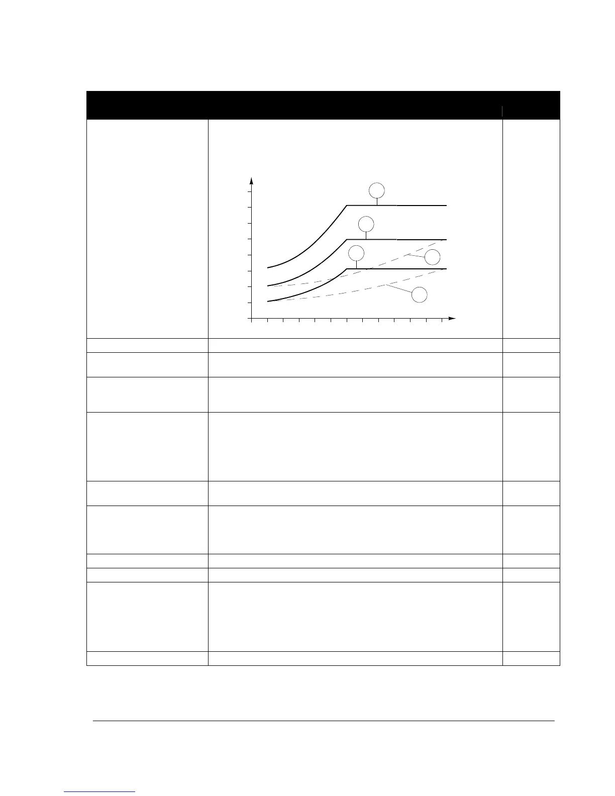
Selects the load curve for the underload function. See parameter 3013
UNDERLOAD FUNC.
T
M
= nominal torque of the motor
T
M
ƒ
N
= nominal frequency of the motor (par. 9907)
(%)
Underload curve types
80
3
70%
60
2
50%
40
1
5
30%
20
4
f
0
ƒ
N
2.4 · ƒ
N
Number of the load curve type in the figure
Selects how the drive reacts to supply phase loss, that is when DC voltage
ripple is excessive.
The drive trips on fault INPUT PHASE LOSS (code: F0022) and the motor
coasts to stop when the DC voltage ripple exceeds 14% of the nominal DC
voltage.
Drive output current is limited and alarm INPUT PHASE LOSS (code: A2026)
is generated when the DC voltage ripple exceeds 14% of the nominal DC
voltage.
There is a 10 s delay between the activation of the alarm and the output
current limitation. The current is limited until the ripple drops under the
minimum limit, 0.3 ·
I
hd
.
The drive generates alarm INPUT PHASE LOSS (code: A2026) when the DC
ripple exceeds 14% of the nominal DC voltage.
Selects how the drive reacts when an earth (ground) fault is detected in the
motor or the motor cable. The protection is active only during start. An earth
fault in the input power line does not activate the protection
Note: Disabling earth (ground) fault may void the warranty.
The drive trips on fault EARTH FAULT (code: F0016).
Defines the fault or alarm level for analog input AI1. If parameter 3001
AI<MIN FUNCTION is set to 1 (FAULT), 2 (CONST SP 7) or 3 (LAST
SPEED), the drive generates alarm or fault AI1 LOSS (code: A2006 or
F0007), when the analog input signal falls below the set level.
Do not set this limit below the level defined by parameter 1301 MINIMUM
AI1.
Value in percent of the full signal range

 Loading...


