PID control macro
This macro provides parameter settings for closed-loop control systems such as
pressure control, flow control, and so on. Control can also be switched to speed
control using a digital input. To enable the macro, set the value of parameter 9902
APPLIC MACRO to 6 (PID CONTROL).
For the parameter default values, see section Default parameter values with different
macros on page 79. If you use other than the default connections presented below,
see chapter Electrical installation, section I/O terminals on page 44.
Note: Parameter 2108 START INHIBIT must remain in the default setting 0 (OFF).
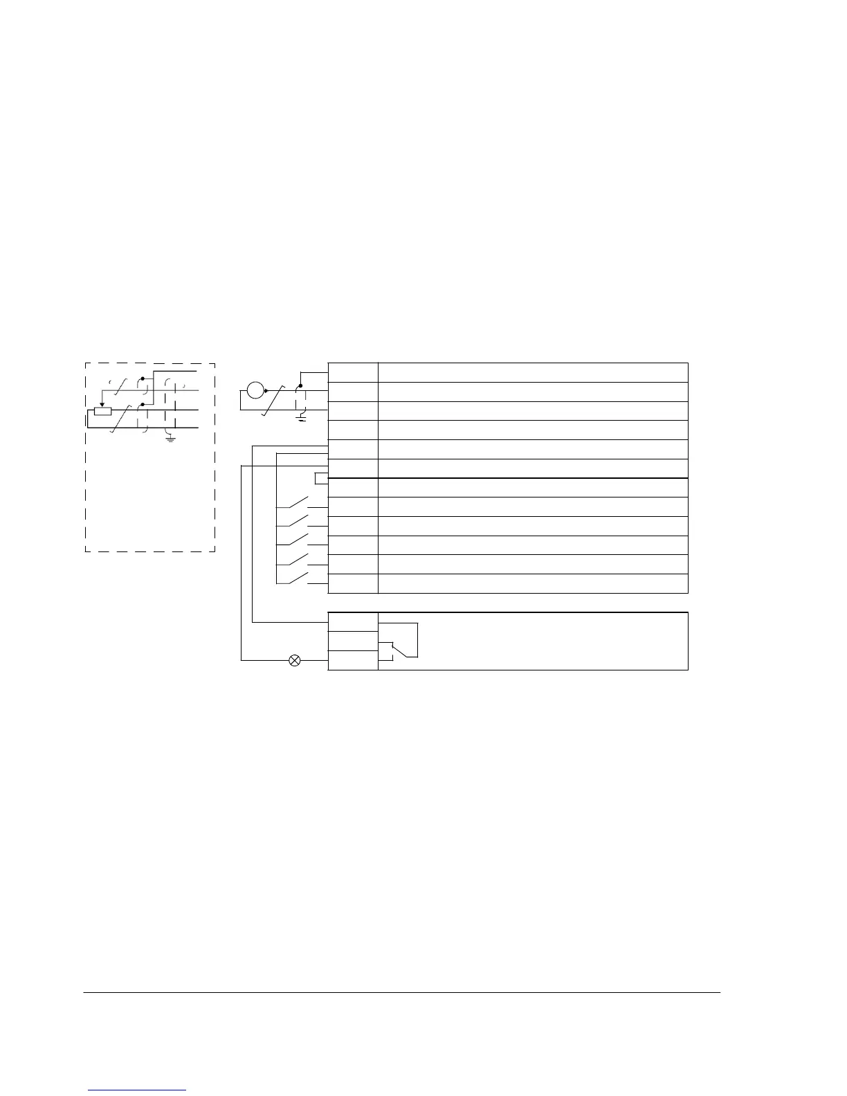
1…10 kohm
Default I/O
connections
2)
I/O connection
3)
SCR Signal cable shield (screen)
AI Process actual value: 4…20 mA
1)
GND Analog input circuit common
+10V Reference voltage: +10 V DC, max. 10 mA
Alternative connection
for AI1. If used, switch
IU selector to U
(2…10 V voltage
signal).
+24V Auxiliary voltage output: +24 V DC, max. 200 mA
GND Auxiliary voltage output common
COM Digital input common
DI1 Stop (0) / Start (1) (Hand)
DI2 Hand (0) / PID (1) control selection
DI3 Constant speed 1: parameter 1202 CONST SPEED 1
DI4 Run enable
DI5 Stop (0) / Start (1) (PID)
Relay connection
4)
COM Relay output
NC
No fault [Fault (-1)]
NO
1)
Hand: frequency reference comes from the
integrated potentiometer
PID: Process reference comes from the
integrated potentiometer.
2)
360 degree grounding under a clamp.
3)
Tightening torque: 0.22 N·m / 2 lbf·in
4)
Tightening torque: 0.5 N·m / 4.4 lbf·in

 Loading...


