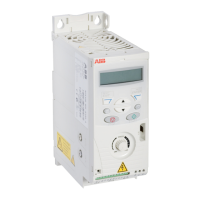
Control connection data
Analog input X1A: AI(1) Voltage signal, unipolar 0 (2)…10 V, R
in
> 312 kohm
Current signal, unipolar 0 (4)…20 mA, R
in
= 100 ohm
Potentiometer reference value
(X1A: +10V) 10 V ± 1%, max. 10 mA, R < 10 kohm
Resolution 0.1%
Accuracy ±1%
Auxiliary voltage X1A: +24V 24 V DC ± 10%, max. 200 mA
Digital inputs X1A: DI1...DI5
(frequency input DI5)
Voltage 12…24 V DC with internal or external supply
Max. voltage for digital inputs 30 V DC
Type PNP and NPN
Input impedance 2.4 kohm
Frequency input X1A: DI5 DI5 can be used either as a digital or as a frequency input.
Frequency input Pulse train 0…16 kHz (DI5 only)
Relay output X1A:
COM, NC, NO
Type NO + NC
Max. switching voltage 250 V AC / 30 V DC
Max. switching current 0.5 A / 30 V DC; 5 A / 230 V AC
Max. continuous current 2 A rms
Wire size Relay connections
I/O connections
Torque Relay connections
I/O connections
1.5...0.20 mm
2
/16...24 AWG
1... 0.14mm
2
/16...26 AWG
0.5 N·m / 4.4 lbf·in
0.22 N·m / 2 lbf·in
Brake resistor connection
Short-circuit protection
(IEC 61800-5-1, IEC 60439-1,
UL 508C)
The brake resistor output is conditionally short-circuit proof by IEC/EN 61800-5-1 and UL
508C. For correct fuse selection, contact your local ABB representative. Rated conditional
short-circuit current as defined in IEC 60439-1 and the short-circuit test current by UL
508C is 100 kA.
Efficiency
Approximately 95 to 98% at nominal power level, depending on the drive size and options
Degrees of protection
IP20 (cabinet installation) / UL open: Standard enclosure. The drive must be installed in a
cabinet to fulfil the requirements for shielding from contact.
IP20 / NEMA 1: Achieved with an option kit (MUL1-R1) including a hood and a connection
box.

 Loading...