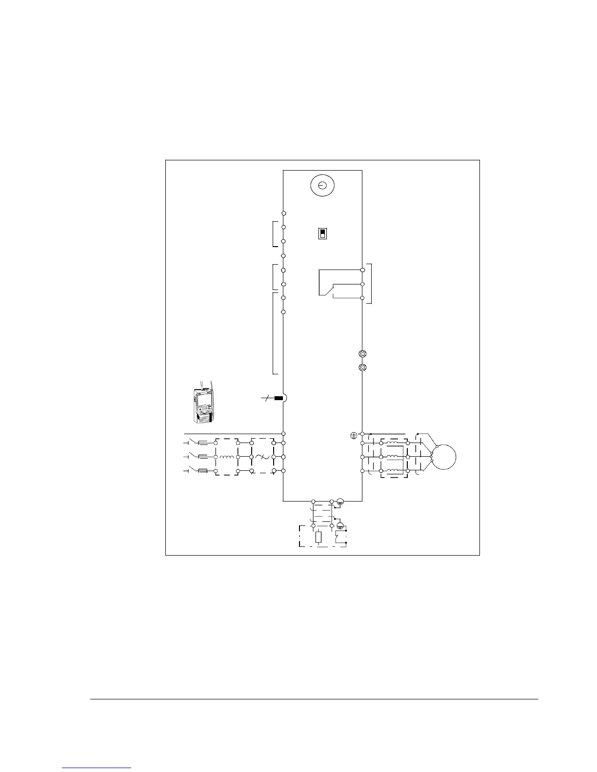
Power connections and control interfaces
The diagram gives an overview of connections. The I/O connections are
parameterable. See chapter Application macros on page 69 for the I/O connections
for the different macros and chapter Electrical installation on page 39 for installation
in general.
Screen
Potentiometer
SCR
S1
Analog input
AI
I
0…10
V
Reference
voltage
+10 V DC, max. 10
mA
Aux. voltage
output
GND
U
AI
+10V
+24 V
COM
+24 V DC, max. 200 mA
GND
COM
DI1
NC
Relay output
250 V AC / 30 V DC / 6 A
NO
PROGRAMMABLE
DIGITAL
INPUTS
DI5 can also be
used
as a frequency
input
DI2
DI3
DI4
DI5
EMC
VAR
EMC filter grounding screw
Varistor grounding screw
6
FlashDrop
PE
PE
L1
L2
U1 U2
V1 V2
M
L3
W1 W2
3-phase
Input
EMC
Brake chopper
Output
AC motor
power
supply,
200…480
V
AC
choke filter
BRK+ BRK-
choke
t°
Brake resistor
Note: For 1-phase power supply, connect power to U1/L and V1/N terminals. For
connecting the power cables, see Connecting the power cables on page 41.

 Loading...


