Parameters in the Long parameter mode
Index Name/Selection Description Def
18 FREQ INPUT
Frequency input signal processing. Digital input DI5 can be programmed as
a frequency input. Frequency input can be used as external reference signal
source. See parameter 1103/1106 REF1/2 SELECT.
1801 FREQ INPUT MIN Defines the minimum input value when DI5 is used as a frequency input. 0 Hz
0…16000 Hz Minimum frequency
1802 FREQ INPUT MAX Defines the maximum input value when DI5 is used as a frequency input. 1000 Hz
0…16000 Hz Maximum frequency
1803 FILTER FREQ IN Defines the filter time constant for frequency input, that is the time within
which 63% of a step change is reached.
0.0…10.0 s Filter time constant
20 LIMITS
Drive operation limits
0.1 s
2003 MAX CURRENT Defines the allowed maximum motor current. 1.8 · I
2N
A
0.0…1.8 · I
2N
A Current
2005 OVERVOLT CTRL Activates or deactivates the overvoltage control of the intermediate DC lin
k.
Fast braking of a high inertia load causes the voltage to rise to the
overvoltage control limit. To prevent the DC voltage from exceeding the limit,
the overvoltage controller automatically decreases the braking torque.
Note: If a brake chopper and resistor are connected to the drive, the
controller must be off (selection DISABLE) to allow chopper operation.
0 = DISABLE Overvoltage control deactivated
1 = ENABLE Overvoltage control activated
2006 UNDERVOLT CTRL Activates or deactivates the undervoltage control of the intermediate DC li
nk.
If the DC voltage drops due to input power cut off, the undervoltage controller
automatically decreases the motor speed in order to keep the voltage above
the lower limit. By decreasing the motor speed, the inertia of the load causes
regeneration back into the drive, keeping the DC link charged and preventing
an undervoltage trip until the motor coasts to stop. This acts as a power-loss
ride-through functionality in systems with a high inertia, such as a centrifuge
or a fan.
0 = DISABLE Undervoltage control deactivated
1 = ENABLE(TIME) Undervoltage control activated. The undervoltage control is active for
500 ms.
2 = ENABLE Undervoltage control activated. No operation time limit.
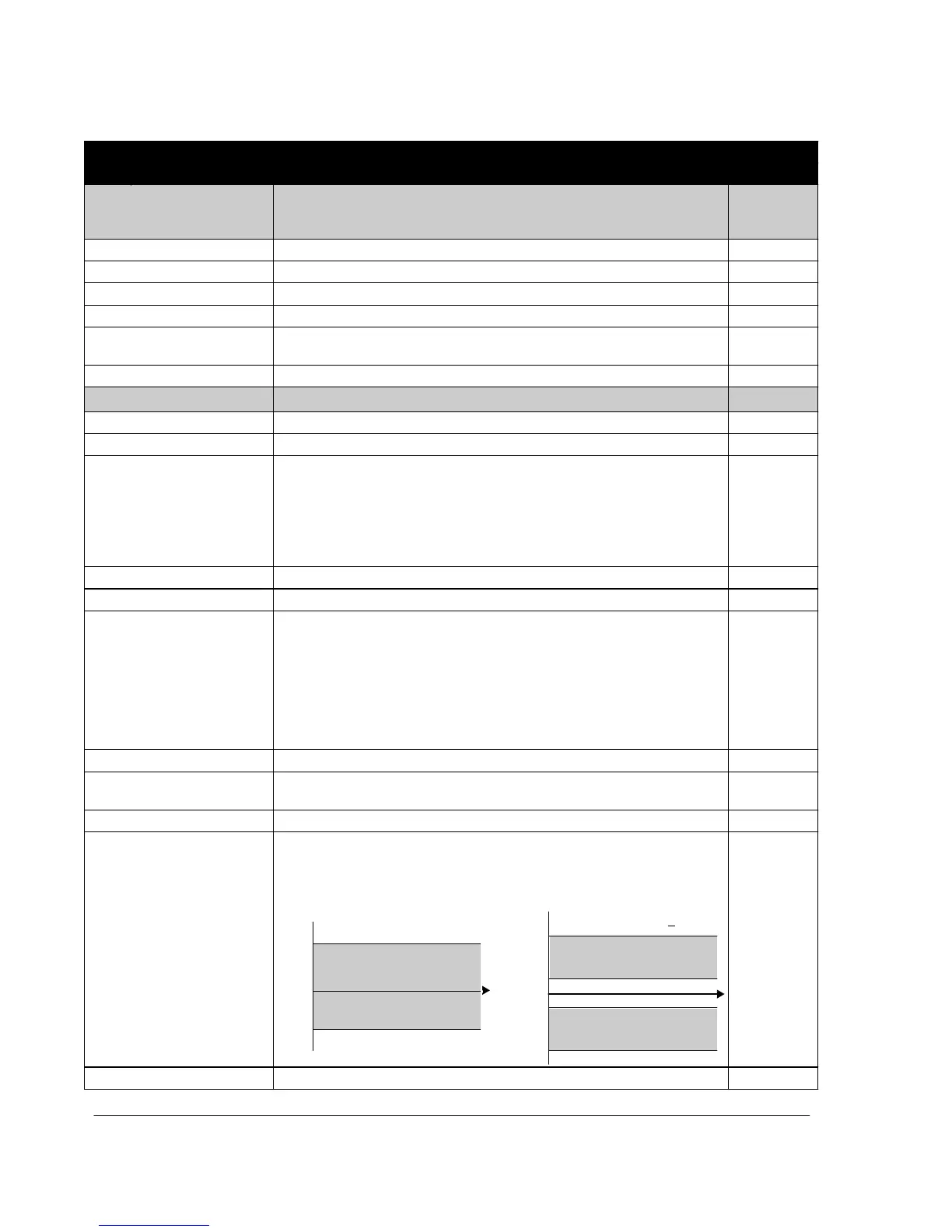
2007 MINIMUM FREQ Defines the minimum limit for the drive output frequency. A positive (or zero)
minimum frequency value defines two ranges, one positive and one negative.
A negative minimum frequency value defines one speed range.
Note: MINIMUM FREQ value must not exceed MAXIMUM FREQ value.
1 = ENABLE
1 = ENABLE
(TIME)
0.0 Hz
f
2008
f
2008
2007
2007 value is > 0
Allowed frequency ra
ng
e
0
0
2007
t
-(2007)
-(2008)
t
Allowed frequency range
-500.0…500.0 Hz Minimum frequency

 Loading...


