Actual signals and parameters
Parameters in the Long parameter mode
Analog input signal processing
Defines the minimum %-value that corresponds to minimum mA/(V) signal for
analog input AI1. When used as a reference, the value corresponds to the
reference minimum setting.
0...20 mA = 0...100%
4...20 mA = 20...100%
Example: If AI1 is selected as the source for external reference REF1, this
value corresponds to the value of parameter 1104 REF1 MIN.
Note: MINIMUM AI value must not exceed MAXIMUM AI value.
Value in percent of the full signal range. Example: If the minimum value for
analog input is 4 mA, the percent value for 0…20 mA range is:
(4 mA / 20 mA) · 100% = 20%
Defines the maximum %-value that corresponds to maximum mA/(V) signal
for analog input AI1. When used as a reference, the value corresponds to the
reference maximum setting.
0...20 mA = 0...100%
4...20 mA = 20...100%
Example: If AI1 is selected as the source for external reference REF1, this
value corresponds to the value of parameter 1105 REF1 MAX.
Value in percent of the full signal range. Example: If the maximum value for
analog input is 10 mA, the percent value for 0…20 mA range is:
(10 mA / 20 mA) · 100% = 50%
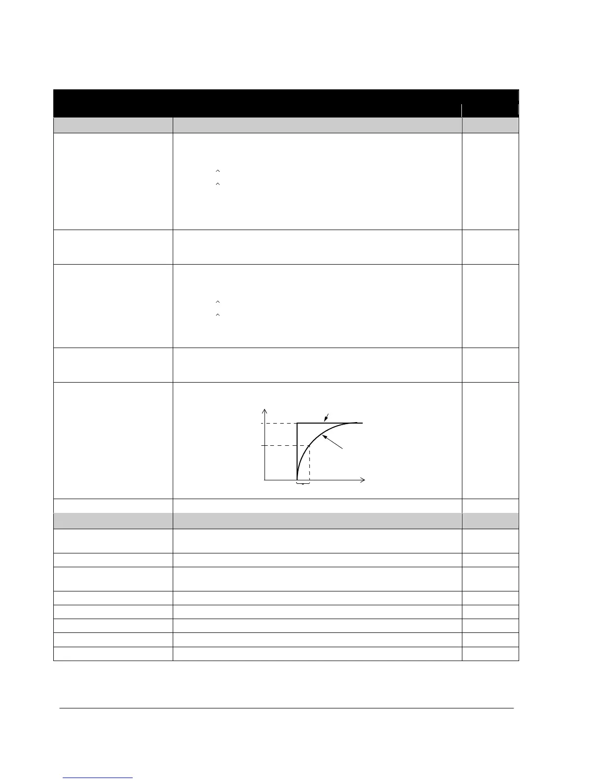
Defines the filter time constant for analog input AI1, that is the time within
which 63% of a step change is reached.
%
Unfiltered signal
100
63
Filtered signal
t
Time co
nst
a
nt
Status information indicated through relay output and relay operating delays
Selects a drive status indicated through relay output RO. The relay energizes
when the status meets the setting.
Ready to function: Run enable signal on, no fault, supply voltage within
acceptable range and emergency stop signal off.
Running: Start signal on, Run enable signal on, no active fault.
Inverted fault. Relay is de-energized on a fault trip.
Motor rotates in reverse direction.

 Loading...


