Connecting the control cables
I/O terminals
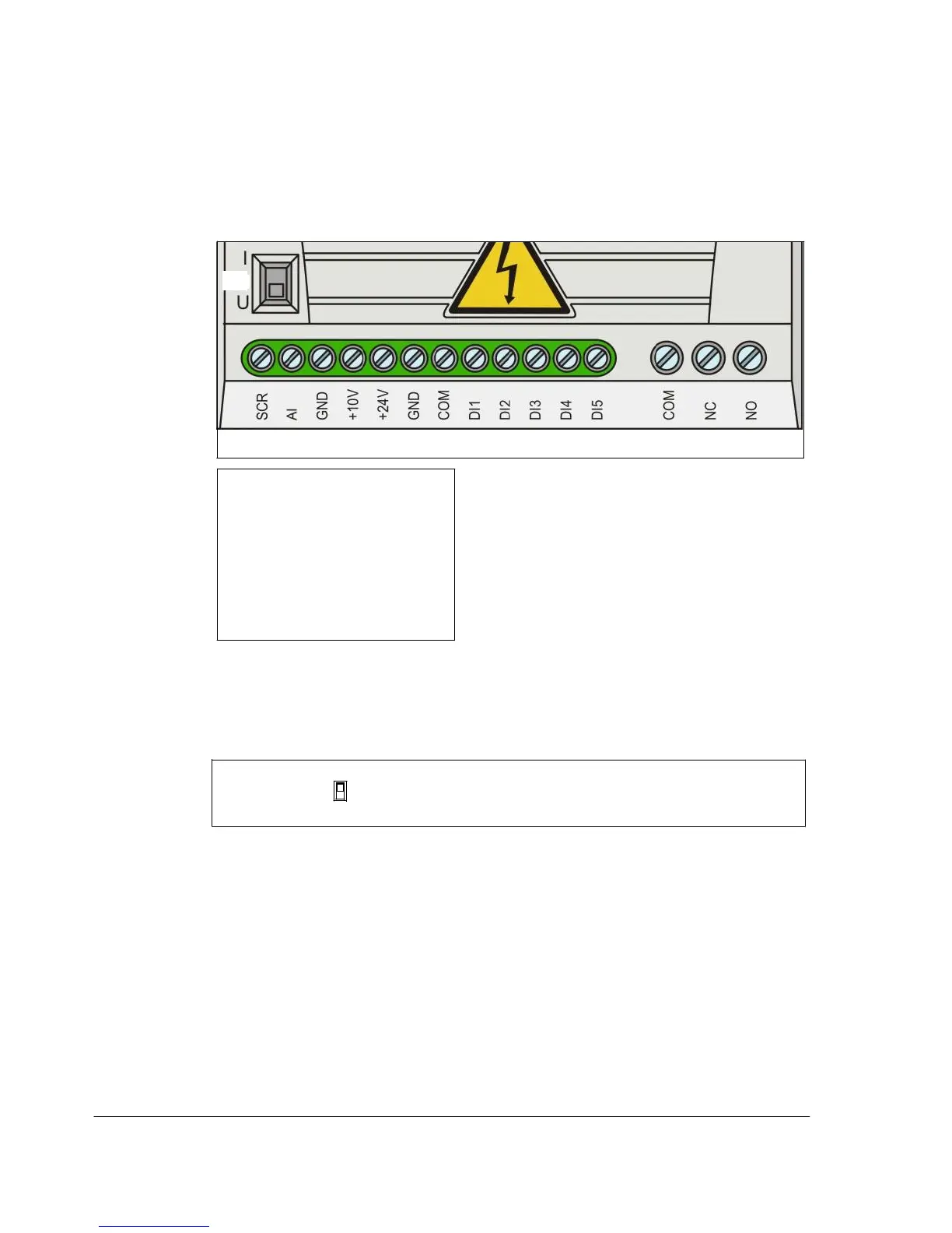
The figure below shows the I/O terminals.
S1
X1A
X1B
X1A: SCR
AI(1)
GND
+10
V
+24 V
GND
COM
DI1
DI2
DI3
DI4
X1B: (RO)COM
(RO)NC
(RO)NO
DI5 digital or frequency input
The default connection of the control signals depends on the application macro in
use, which is selected with parameter 9902 APPLIC MACRO. See chapter
Application macros on page 69 for the connection diagrams.
Switch S1 selects voltage (0 [2]…10 V) or current (0 [4]…20 mA) as the signal type
for analog input AI. By default, switch S1 is in the current position.
I
Top position: I (0 [4]…20 mA), default for AI
U
Bottom position: U (0 [2]…10 V)
If DI5 is used as a frequency input, set group 18 FREQ INPUT parameters
accordingly.

 Loading...


