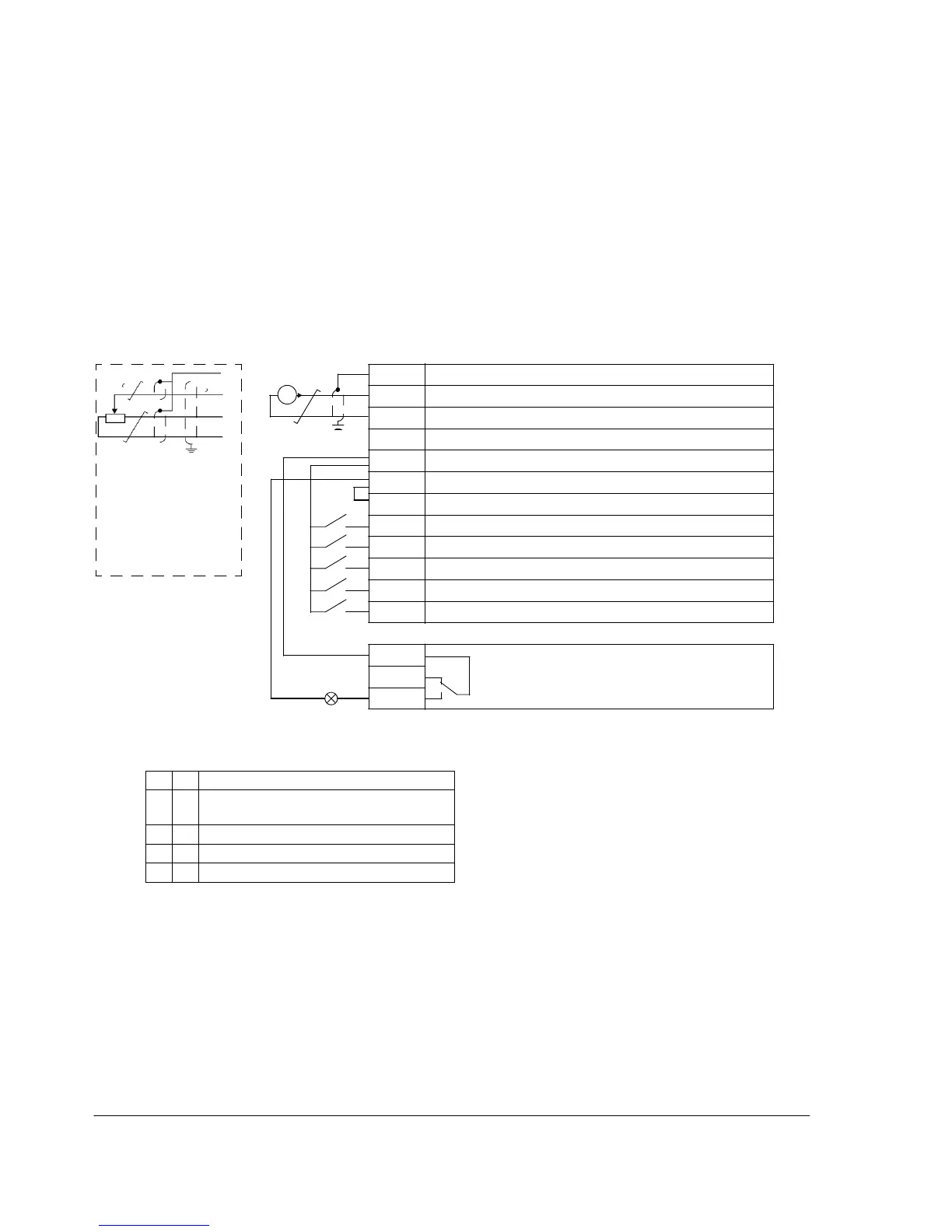
Default I/O connection diagram
The default connection of the control signals depends on the application macro in
use, which is selected with parameter 9902 APPLIC MACRO.
The default macro is the ABB standard macro. It provides a general purpose I/O
configuration with three constant speeds. Parameter values are the default values
given in section Default parameter values with different macros on page 79. For
information on other macros, see chapter Application macros on page 69.
The default I/O connections for the ABB standard macro are given in the figure
below.
1…10 kohm
Alternative connection
for AI1. If used, switch
IU selector to U
(0…10 V voltage
signal).
3)
I/O connection
4)
SCR Signal cable shield (screen)
AI Frequency reference: 0…20 mA
GND Analog input circuit common
+10V Reference voltage: +10 V DC, max. 10 mA
+24V Auxiliary voltage output: +24 V DC, max. 200 mA
GND Auxiliary voltage output common
COM Digital input common
DI1 Stop (0) / Start (1)
DI2 Forward (0) / Reverse (1)
DI3 Constant speed selection
1)
DI4 Constant speed selection
1)
DI5 Acceleration and deceleration selection
2)
Relay connection
5)
COM Relay output
NC
No fault [Fault (-1)]
NO
1) See parameter group 12 CONSTANT SPEEDS: 2) 0 = ramp times according to parameters 2202
ACCELER TIME 1 and 2203 DECELER TIME 1.
1 = ramp times according to parameters 2205
ACCELER TIME 2 and 2206 DECELER TIME 2.
3) 360 degree grounding under a clamp.
4) Tightening torque: 0.22 N·m / 2 lbf·in
5) Tightening torque: 0.5 N·m / 4.4 lbf·in

 Loading...


