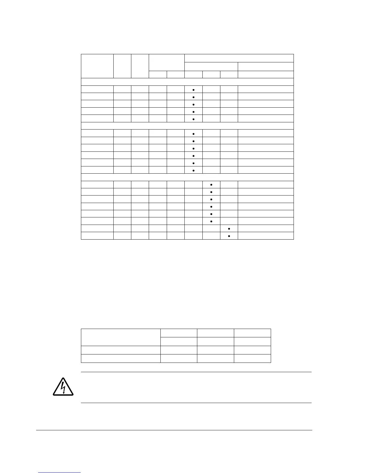
Selection table by resistor type
1-phase U
N
= 200…240 V (200, 208, 220, 230, 240 V)
3-phase U
N
= 200…240 V (200, 208, 220, 230, 240 V)
3-phase U
N
= 380…480 V (380, 400, 415, 440, 460, 480 V)
1)
E=EMC filter connected (metal EMC filter screw installed),
U=EMC filter disconnected (plastic EMC filter screw installed), US
parametrization.
2)
Braking time = maximum allowed braking time in seconds at P
BRmax
every
120 seconds, at 40 °C ambient temperature.
00353783.xls J
Note: The brake resistors listed in the table are available in Europe. They do not apply to the USA. Contact
your local ABB representative for more information.
Symbols
R
min
= minimum allowed brake resistor that can be connected to the brake chopper
R
max
= maximum allowed brake resistor that allows R
max
P
BRmax
= maximum braking capacity of the drive, must exceed the desired braking power.
WARNING! Never use a brake resistor with a resistance below the minimum value
specified for the particular drive. The drive and the internal chopper are not able to
handle the overcurrent caused by the low resistance.

 Loading...


