Update notice
13
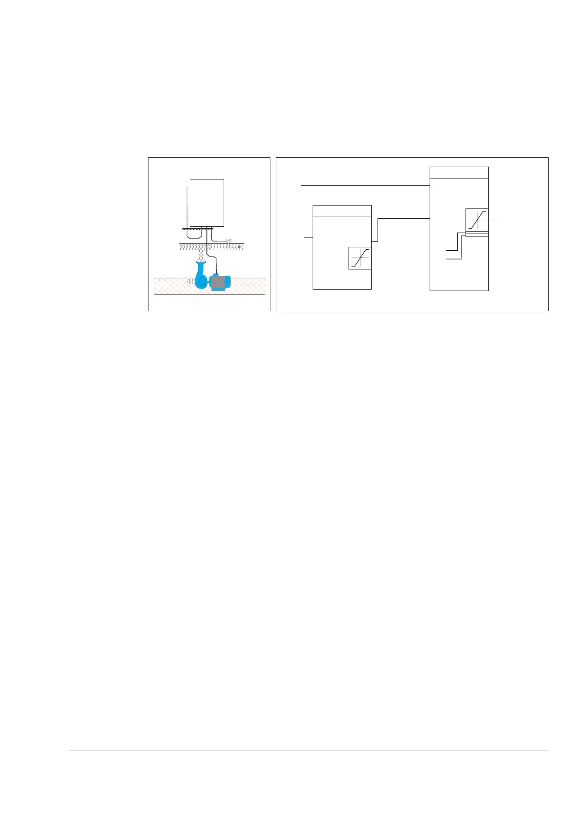
Pressure boost pump
The figure below shows an application example: The controller adjusts the speed of
a pressure boost pump according to the measured pressure and the set pressure
reference.
How to scale the PID actual (feedback) signal 0…10 bar / 4…20 mA
PID feedback is connected to AI1 and 4016 ACT1 INPUT is set to AI1.
1. Set 9902 APPLICATION MACRO to 6 (PID CONTROL). Check scaling: 1301
MINIMUM AI1 as default 20% and 1302 MAXIMUM AI1 as default 100%. Check
that 1106 REF2 SELECT is set to 19 (PID1OUT).
2. Set 3408 SIGNAL2 PARAM to 130 (PID1 FBK).
3. Set 3409 SIGNAL2 MIN to 0.
4. Set 2310 SIGNAL2 MAX to 10.
5. Set 3411 OUTPUT2 DSP FORM to 9 (DIRECT).
6. Set 3412 OUTPUT2 UNIT to 0 (NO UNIT).
7. Set 4006 UNITS to 0 (NO UNIT).
8. Set 4007 UNIT SCALE to 1.
9. Set 4008 0% VALUE to 0.
10. Set 4009 100% VALUE to 10.
How to scale the PID setpoint signal
1. Set 4010 SET POINT SEL to 19 (INTERNAL).
2. Set 4011 INTERNAL SETPNT to 5.0 ("bar" is not displayed on the drive control
panel) as an example.
For detailed parameter descriptions, see the related parameters in ACS150 user’s
manual (3AFE68576032 [EN]).
AC T PA R FUN C DRIV E
E NT E R
LO C
RE M
RE SET
RE F
A C S 6 0 0
0 . . . 1 0 b a r
4 . . . 2 0 m A
3
3
2
PID
ref
k
ti
td
i
dFiltT
errVInv
oh1
ol1
%ref
PIDmax
PIDmin
Example:
PID control block diagram
%ref = 4010
Pressure boost pump
ACS150
...
Actual values
AI1
AI2
IMOT
.
.
.
4001
4002
4003
4004
4005
4014
4021
Frequency
reference
0…10 bar
4…20 mA