Electrical installation
38
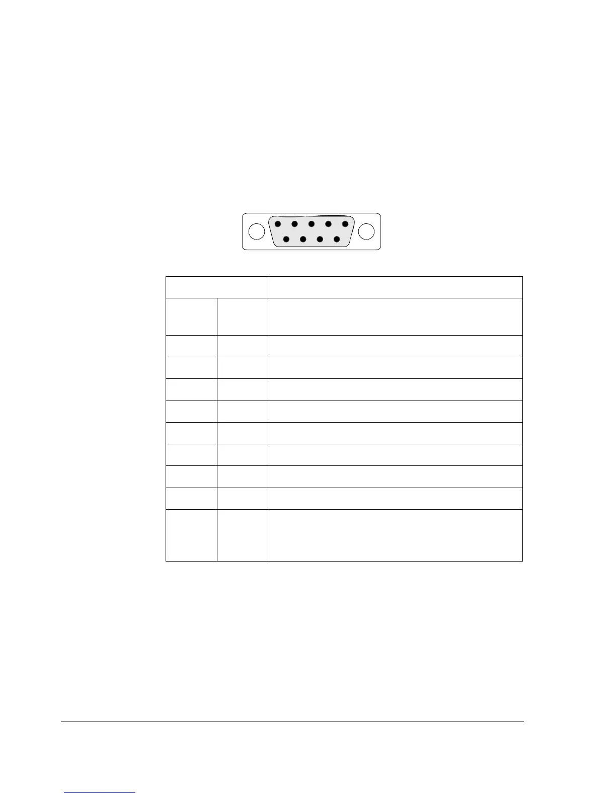
PROFIBUS connection
The bus cable is connected to connector X1 on the FPBA-01.
The connector pin allocation described below follows the
PROFIBUS standard.
X1 Description
1 SHLD Alternate cable shield connection. Connected
to connector housing.
2 Not used
3 B Data positive (Conductor 1 in twisted pair).
4 RTS Request To Send
5 GND_B Isolated ground
6 +5V_B Isolated 5V DC voltage supply (30 mA max.)
7 Not used
8 A Data negative (Conductor 2 in twisted pair).
9 Not used
Housing SHLD PROFIBUS cable shield. Internally connected
to GND_B via an RC filter and directly to
CH_GND (chassis).
+5V and GND BUS are used for bus termination.
RTS is used in some equipment to determine the direction of
transmission. In typical applications, only the line A, line B and
shield are used.
X1
1
69
5