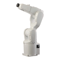
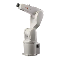
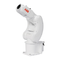
Fitting equipment on base and upper arm
The illustration shows the fitting holes available for fitting extra equipment on the
base and upper arm of the robot.
25±0.15
2xM4 8
25 ±0.15
2xM4 8
A
B
53
187
D
C
xx0900000203
Load area base, max load 0.5 kg (on each side)A
Load area upper arm, max load 0.3 kgB
Max. 172 mmC
Max. radius 75 mmD
NOTE! Fitting holes at the base of the robot are placed on each side.
Continues on next page
Product manual - IRB 120 73
3HAC035728-001 Revision: N
© Copyright 2009-2017 ABB. All rights reserved.
2 Installation and commissioning
2.3.4 Fitting equipment on robot
Continued
 Loading...


