NoteAction
xx1700000978
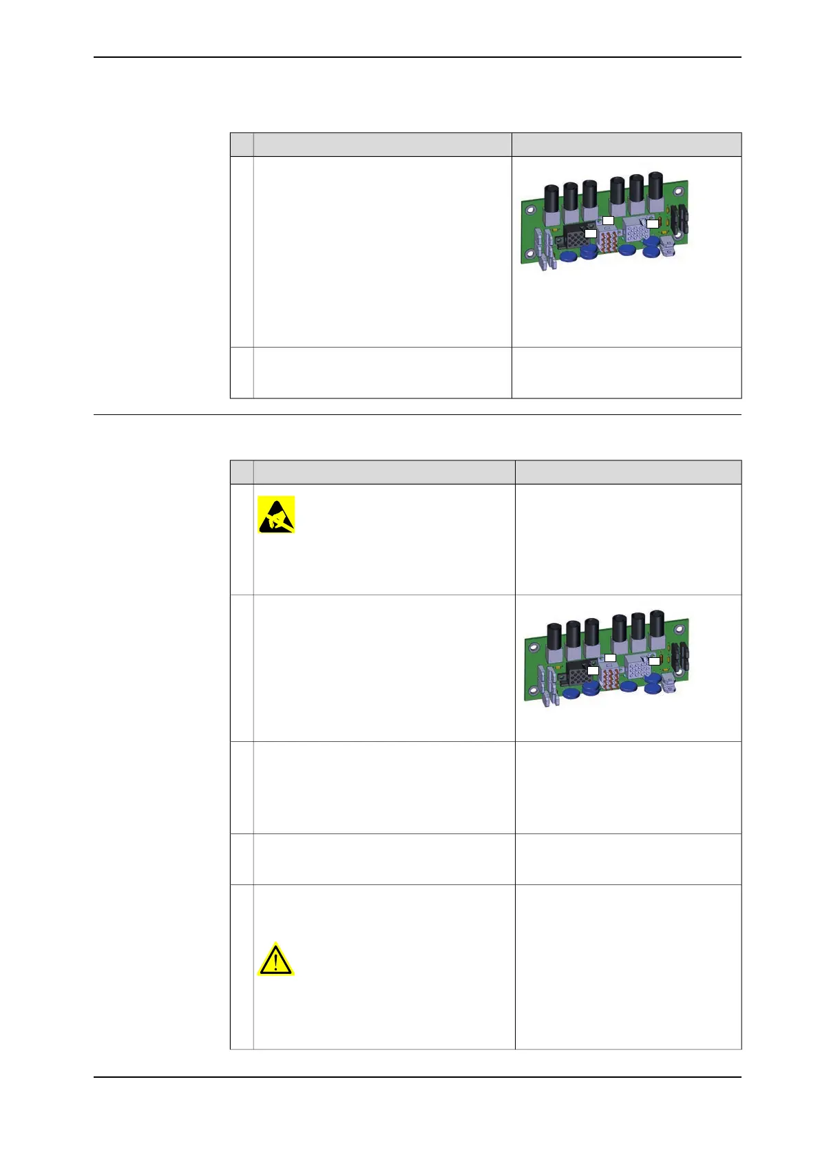
Disconnect the connectors X8, X9 and X10
from the brake release board.
7
Location of the brake release unit is
shown in the figure Location of brake
release board on page 169.
Remove the brake release board from the
bracket by removing the four attachment
screws.
8
Refitting, brake release board
Use this procedure to refit the brake release board.
NoteAction
ELECTROSTATIC DISCHARGE (ESD)
The unit is sensitive to ESD. Before handling
the unit read the safety information in section
The unit is sensitive to ESD on page 31
1
xx1700000978
Connect the connectors X8, X9 and X10 to the
brake release board.
Be careful not to damage the sockets or pins.
Make sure the connector and its locking arms
are snapped down properly.
2
Maximum tightening torque: 5 Nm.Fasten the brake release board on the bracket
with the attachment screws.
Make sure the board is positioned as straight
as possible on the bracket! The push buttons
can otherwise get jammed when the SMB
cover is refitted.
3
Shown in the figure Location of brake
release board on page 169.
Art. no. is specified in Required equip-
ment on page 170.
Refit the complete brake release board (includ-
ing brake release board and bracket) to the
SMB recess with the two attachment screws.
4
Verify that the robot cabling is positioned cor-
rectly, according to previously taken pic-
ture/notes.
WARNING
Screened cables must not get in contact with
the brake release board after installation.
Eliminate all risks of contact between screened
cables and the brake release board.
5
Continues on next page
Product manual - IRB 460 171
3HAC039842-001 Revision: P
© Copyright 2012-2018 ABB. All rights reserved.
4 Repair
4.3.4 Replacing the brake release board
Continued

 Loading...


