NoteAction
Fit 14 of the 16 attachment screws before the
arm system is completely lowered.
11
This is done in order to be able to attach all
screws into the threads correctly.
Replace the guide pins with the remaining
attachment screws and secure the complete
arm system to the base with its attachment
screws and washers.
12
Lower the arm system completely.13
Tightening torque:
• 120 Nm.
Secure the complete arm system with its at-
tachment screws.
14
See Replacing cable harness, lower end
(axes 1-3) on page 147.
Refit the cable harness in the base and the
frame.
15
See Replacing motor, axis 1 on page 285.Refit the axis 1 motor.16
xx1000001302
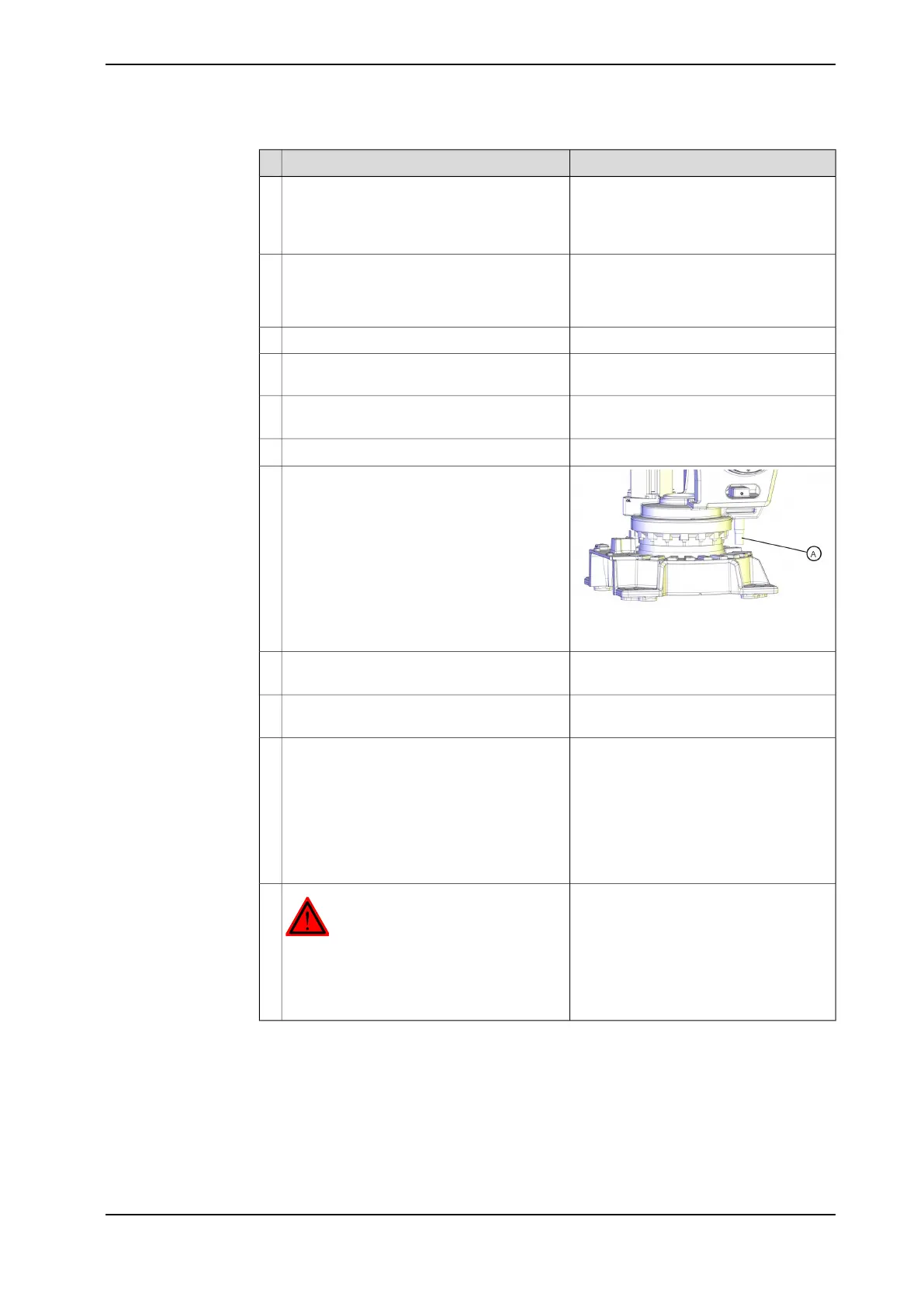
Refit the mechanical stop pin to the frame.17
A: Mechanical stop pin
See Performing a leak-down test on
page 140.
Perform a leak-down test of the axis 1 gear-
box.
18
See Changing oil, axis-1 gearbox on
page 122.
Refill the axis 1 gearbox with lubricating oil.19
Pendulum Calibration is described in
Operating manual - Calibration Pendulum,
enclosed with the calibration tools.
Recalibrate the robot.20
Axis Calibration is described in Calibrat-
ing with Axis Calibration method on
page 357.
General calibration information is included
in section Calibration on page 347.
DANGER
Make sure all safety requirements are met
when performing the first test run. These are
further detailed in the section First test run
may cause injury or damage on page 26.
21
Product manual - IRB 460 181
3HAC039842-001 Revision: P
© Copyright 2012-2018 ABB. All rights reserved.
4 Repair
4.3.5 Replacing the base, including axis 1 gearbox
Continued

 Loading...


